I wanted to improve our doorbell... Yes, that is dull.
But the main change is not the bell (a nice, old style bell in the kitchen, which is driven by a Shelly, and the sitting room, and flashing lights in bedrooms and hot tub), or the bell push itself as such, but a sign on the door by the bell.
We used to have a simple brass "please ring the bell" sign, pointing to the bell push. Still, too many people knock instead.
Push the button
So the idea is a sign, and additional bell push right by it, on the actual door. The sign has the house name and number and road name - that itself may help as we get parcels for the same number in the next road often, and they get ours. But a sign saying ring the bell with a hand pointing to the bell push right by the sign.
The magic happens when they push the bell (either the new or old bell push) - the sign lights LEDs on the back and changes. The basic option is like this...
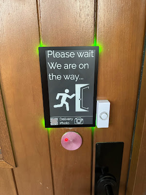
I included a barcode with date time and postcode for photos when leaving a parcel.
Seasons greetings
I also decided it may be a fun idea to change the message, add Christmas tree for now, and so on, but even regionalise the message...

The idle message can be updated and made seasonal, I may even automate based on date, but also the message shown when you press the button can vary depending on circumstances. This saves me putting a sign on the door when we are out - which is a notice to everyone that we are, well, out. The message for when we are out ("leave parcels behind the double gates") is only shown when someone pushes the bell. Indeed other messages can be set if needed.
Let there be light
The main way it decides what to show is based on lights. Yes, that seems crazy, but is incredibly simple when almost all lights are Shelly running tasmota and reporting to MQTT. I can track light states. I have a stairs light which only gets turned off when the alarm is set (we are out). I also track the hall light, which is an easy way I can indicate "we are busy, leave by the door" for when I am in the hot tub, etc. Indeed, if I change a light when the message shown updates in real time, so if in the hot tub I can remote turn off the hall light from my phone when the bell rings.
I also have Mastodon DMs for the bell, with exact time stamps to make easy to find in CCTV.
It also means control of the status display is something my wife can also easily understand and change if she wants, just using light switches.
Making a board
Obviously I designed my own circuit board for this. It works with a waveshare 7.5" e-paper display.

It sticks to the back of the board, has an ESP32-S3 with wifi, USB connectors, and big solder tabs for wires for power and the bell itself. It was designed so it could be set in resin even (though that seems to break the e-paper, possibly by getting in the FPC connector). So a bare board with acrylic spray for now.
No-bell prize
It did not work. The screen did not update properly. I was disappointed to say the least.
 |
| Old |
 |
| New |
The fix was to change the inductor and make it work, yay, no no-bell prize for me now.
So, finally, it works!
Update: The only reason this board is this size is because it has LEDs (one in each corner) do fits the 7.5" e-paper. If not then it could use a much smaller board, which I have also designed. But the new version of this larger board now has 24 LEDs, given that the LEDs are the only reason for the larger board this makes sense, but it may be a slight power issue as they are 10mA when white, so some testing may be necessary.
Update: I love the fact I have been accused of "nerd sniping" Bloor. He got one of these 7.5" panels with the waveshare HAT, and somehow he totally messed up the simple task of the FPC connectors, so much he broke several of them, and then managed to crack the display trying to get one working, and threw it all away. I come in and not only have no problem with the connectors, but then I don't just use the 7.5" panel and HAT with no problem, but make my own better PCB, and a new smaller PCB, and a version 2 of both boards, and a working door sign, and now even listing on Amazon! Is that "nerd sniping", or am I bad?


