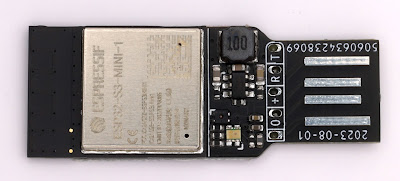
2023-08-30

What counts as R&D?

One of the things a company can do in the UK is claim some tax benefits for spending some of the company resources on R&D. It is an incentive for companies to do R&D.

As a company that does a lot of R&D, we work with a really good agency on this, and get some tax credit. This works well, and is indeed an incentive for us to do more R&D.

This year the rules have changed slightly, and I noted a couple of them. It is all a bit open to interpretation, but a couple of the points seem a bit odd.

Open source

For a start, if we, as a company, did some purely open source stuff that was not direct benefit to us - by way of giving back to the open source community, it seems that would not qualify for R&D tax credits. It has to benefit the company. Thankfully this is not really a problem as pretty much all of the open source stuff we do is used in house and so benefits us directly as well. Some of the stuff we don't use in house, is actually stuff we then make and sell, so a benefit to us. But it is a disincentive for doing something purely open source.

Super human engineers

The other one that is odd is that things are not R&D if they would be apparent to a competent engineer in the field with publicly available information.

Well, we employ competent engineers. everything they do is apparent to a competent engineer. It almost sounds like, to be valid R&D, we need super human engineers, which seems a bit much.

We had a lot of discussion on this - one thing is the "publicly available information". This has meant we have focused a lot on things where the publicly available information is wrong or incomplete. And notably where what was "apparent" to the competent engineer was in fact wrong when tried.

Though one other aspect is that we think we can validly say that anything we are doing based on closed source designs and code is something that qualifies because that closed source is not publicly available information. None of it would be apparent to our competent engineers without access to that closed source information. So again, this seems to be discouraging open source.

Even so, the end result was a good meeting today, and plenty of R&D work.

2023-08-25

Amazon done wrong

We sell on Amazon, and for that I'll apologise at the start, but it does provide some convenience to some customers and mostly works.

A few weeks ago we got an email saying we have to upload dome documents or they will close the account, and several ongoing reminders. Oh shit...

The problem is that the staff, including me, have a login to the seller account and can do 99% of things on it, as needed, but we could not do this as it had to be the main seller account. OK, so log in to that. Easy.

Except it wants to SMS a number to one of two numbers. Both were set up (and so worked at the time), but are 01344 (i.e. landline) numbers, and between when set up and now Amazon have obviously fucked up their SMS stuff and cannot SMS either.

The interworking of SMS really is a shit show and needs OFCOM to actually do its job and ensure it works properly.

But they also for calling them with a code - yay - except that also does not work - no clue why. Both numbers valid for SMS and calls, and they do neither.

So I tried the "remove 2FA" and sent pictures of passport, or something. My accounts manager did the same several times. No joy.

Every single chat was just crazy, and got to being daily. I mean I am tempted to publish them - they are so mad. One of them insisted I wait 24 hours after trying before contacting them - I said I had done that - he asked why I did not contact them after waiting 24 hours - and I explained I did - this is me contacting them!! The chats were like that. I don't like to judge people as "stupid", honest, people are only sensible in the areas they know, and that applies to all of us. But really, these chats were "special".

Just to be clear - the only reason I could "chat" at all is I had a working amazon account from which to chat. If not I would be screwed.

I have my case handled and referred to these, all of which did not reply at all!

  • Internal escalation team
  • Account recovery team
  • External escalation team

I finally got someone that insisted that another "remove 2FA" should work, and I tried it, and, well, it did. But the instructions were clear - once done I could log in with just a password.

This was a lie. I logged in, and it said "Enter verification code. For your security, we've sent the code to your phone ***-***-**23" which basically means 2FA, so not removed, but also a number I don't know. Not either of the two numbers before.

Many more chats. No way to progress this. Doing the "remove 2FA" again stalled as it needs the code sent to *23 to get as far as uploading a driving licence even. I kept on, emailed in again, and finally it changed.

Now I have option for OTP by email or by SMS to *23, yay, but then it again does "Enter verification code. For your security, we've sent the code to your phone ***-***-**23" as well. So email and SMS now! (yes, when I got SMS working it wanted email too, so yes, both now needed!).

Had there not been an actual mobile *23 I really think we would be screwed. They have zero way to sort this from what I can see. Removing 2FA is "still do 2FA using a *main* mobile number" which you cannot change until you log in!

Turns out, after some research, checking staff lists, and pestering someone on leave and at a party (really, thank you Mike), I found someone that had a number ending in 23, and they were indeed what was on Amazon. So they let me know the code. Yes, that is being fixed, they should not have been on the main login, really. History from when first set up.

So finally I am in - it took a couple of attempts, but now the 2FA is sorted.

Phew.

So back to step 1. What is it they need.

Well this...

Yep, it is a sort of Farage test I think!

Obviously I click Agree and submit.

And, well, predictable...

So, err...

So another chat, and really, I am at a loss on this chat...

Ok, long winded, but basically no clue why this was an issue "not understandable" somehow, and actually, no, there is no way to upload a screenshot.

Eventually got an email and replied with a screenshot. It is a "don't reply to this" email address, FFS.

2023-08-21

LIGHT HAS A SPEED - SO WHY NOT DARK?

I was looking at today's xkcd, and am reminded of a Terry Pratchett quote: [The science of Discworld, Terry Pratchett, Ian Stewart & Jack Cohen, ISBN 9780091886578, chapter 22 "Things That Aren't"]

LIGHT HAS A SPEED - SO WHY NOT DARK?

It's a reasonable question. Let's see where it leads.

In the 1960s a biological supply company advertised a device for scientists who used micro-scopes. In order to see things under a microscope, it's often a good idea to make a very thin slice of whatever it is you're going to look at. Then you put the slice on a glass slide, stick it under the microscope lens, and peer in at the other end to see what it looks like. How do you make the slice? Not like slicing bread.

The thing you want to cut - let's assume it's a piece of liver for the sake of argument - is too floppy to be sliced on its own. Come to think of it, so is a lot of bread.

You have to hold the liver firmly while you're cutting it, so you embed it in a block of wax. Then you use a gadget called a micro-tome, something like a miniature bacon-slicer, to cut off a series of very thin slices. You drop them on the surface of warm water, stick some on to a microscope slide, dissolve away the wax, and prepare the slide for viewing. Simple ...

But the device that the company was selling wasn't a microtome: it was something to keep the wax block cool while the microtome was slicing it, so that the heat generated by the friction would not make the wax difficult to slice and damage delicate details of the specimen.

Their solution to this problem was a large concave (dish-shaped) mirror. You were supposed to build a little pile of ice cubes and  'focus the cold' on to your specimen.

Perhaps you don't see anything remarkable here. In that case you probably speak of the 'spread of ignorance', and draw the curtains in the evening to 'keep the cold out' - and the darkness.

It occurs to me that it would surely work as you would expect. Whilst you cannot focus cold on to something, you can cover part of the area that would radiate heat from the environment to something with a mirror, and that mirror pointing at ice cubes means that not as much heat is radiating from the ice cubes via the mirror to the target as would be otherwise. But heat from the target is radiating to the ice cubes that absorb that heat. The net flow of heat would be from the sample to the ice cubes for a large chunk of the area surrounding the sample.

But this would mathematically be the same as considering cold radiating from the ice cubes to the target via the mirror. I suspect the maths works out exactly as you would expect for focusing cold just the same as it does for electron holes.

Yes?

2023-08-11

ESP32-S3-MINI-1 GPIO

I now have a few boards, including a general test board...

The ESP32-S3-MINI-1 has 39 GPIO pins, though the data sheet defines that one (GPIO26) is reserved when using PSRAM (e.g. ESP32-S3-MINI-1-N4R2).

Unlike the S1 boards, the GPIO are all available as input or output, making its very flexible. But as always there are some caveats on GPIO usage.

The following relates specifically to the ESP32-S3-MINI-1 module only.

Restricted use:

GPIO0

GPIO0 is the main strapping pin that defines BOOT mode. If low at startup the device enters boot mode. It is pulled up internally so can be left unconnected. This means you cannot use this as an input if there is any chance of the input being low at start up. It can be freely used as an output.

By far the most common usage for GPIO0 is connection to the cathode of a status LED.

GPIO19/20

By default these are USB. This may make them not ideal to use for inputs. Note that they can be configured not to be USB by a fuse setting, but will be USB on an unconfigured module. As such it is probably best to use for USB.

GPIO26

The cannot be used with a PSRAM module, e.g. ESP32-S3-MINI-1-N4R2. It can be used if not PSRAM, e.g. ESP32-S3-MINI-1-N8.

GPIO43/44

By default the boot serial console uses GPIO43 and GPIO44. This means GPIO43 is configured as an output at start up. There are settings to stop any actual output on this. This means it cannot be used as a driven input without at least a resistor to handle the clash at startup. GPIO44 is an input so can be used for any purpose without any problems generally.

GPIO46

GPIO46 only matters when in BOOT mode (GPIO0 low) and in such case must be low. It is pulled low by default so an be unconnected. But do not use this as an input that could be high at startup in BOOT mode. It can safely be used as an output.

Caution:

GPIO3

This is defined as a strapping pin, and is floating by default. However it is only relevant depending with some specific eFuse settings related to JTAG operation. When using the default USB JTAG working, this pin can be used as a general input or output.

GPIO45

GPIO46 impacts the voltage used for SPI, but depends on EFUSE_VDD_SPI_FORCE. But this efuse is already set by default on this module, which means GPIO45 is ignored. It can therefore be used as an input or output.

Serial or USB console?

The S3 modules have two ways you can operate the console - the normal serial (UART), and USB.

USB

The default USB working is as USB JTAG and Serial console. This allows flashing and debug console, and a lot more debugging using JTAG and OpenOCD. This is by far the simplest way to manage the module and what I would recommend.

In most cases my boards have USB, either a printed tab for USB-A or a USB-C connector, but in the rare cases they do not, it is simple to include a header for USB to work with a lead.

This nicely fits under the module itself, with no vias, so takes no space and so no component cost. I deliberately spaced as 0.1" header and with a polarity to avoid confusion.

Apart from using JTAG, the USB serial is not really serial, so is way quicker for flashing code than using the real serial port.

There is one small snag...

It is possible to use an efuse, and more importantly, it is possible for the application to turn off the USB pins. This can even be inadvertent (I have done this, loading code for a different board which had an LED on GPIO19). This then means you cannot use the USB port at all, so cannot reset or load code or anything.

For this one reason, it is always useful to have a fallback.

Serial

The other approach for flashing and console is the conventional serial port. For this you need to have at least Tx and Rx (GPIO43/44) pins, and boot mode (GPIO0), and a means to reset (EN). You could use power on as the reset and keep it to just 5 pins. I use a header that works the same as the Shelly 1 and so can use my Tasmotiser board.

This also fits under the processor rather nicely with no need for vias, and no component cost. In fact, it can fit under the processor along with a USB header...

2023-08-08

ESP32-S3

I have worked through a few of these processors - starting with the ESP8266. I moved to the ESP32 quickly and have not looked back - initially with the WROOM module (which can be hand soldered), to the PICO module (which is smaller and needs solder stencil and paste).

But finally the ESP32-S3 (version 3 of the silicon) is available as a module, the ESP32-S3-MINI-1, so I am finally starting to use that. The fact that the ESP32-PICO-MINI seem to suddenly be out of stock, seems like the time to upgrade designs.

The S3 has several improvements which may be useful.

Size matters

A key difference is size. The ESP32-PICO-MINI (i.e. S1) is 13.2mm square plus antenna, but the ESP32-S3-MINI is 15.4mm square plus antenna. So 2.2mm wider and longer.

For almost all of my designs this slight change does not matter, and indeed, for some the other changes actually make things smaller. There are exceptions - the module to go in to the case of a Galaxy keypad may be too big as there is very little space.

However, there is one useful side effect of this extra size. I have a small 5 pad footprint for serial programming - it uses the same 5 pins as the Shelly, and is pretty much the minimum you can have for serial programming and debug (see on image above on the right of the components). Now the module is slightly bigger than can actually fit behind the module, so effectively taking no extra space on a single signed board. This is one of those small details that saves space - e.g. the design show above is now a couple of mm shorter as a result.

General purpose I/O

Another change is the GPIO. The S1 modules have fewer GPIO (27), but several of them are input only - all of one side of the module has no output GPIO. There are also a number of NC pins.

The S3 has more GPIO (39), and all of them are input and output. There are no NC pins (apart from GPIO26 when using the PSRAM based module). This means all three sides of the module have lots of usable GPIO. This is perfect for tracking as you can easily track to the nearest convenient GPIO, which saves space.

USB

This is where it gets both interesting and slightly disappointing.

The S3 has USB built in, so direct connection of D- and D+ pins to specific GPIO. It can be disabled, and it can be used in s/w as USB server or client side as needed, which is very cool. This saves space on many designs if no UART needed.

The default, starting point, is USB JTAG with USB serial. This appears on my Mac, for a totally un-programmed module, as a USB serial port. I can connect to it and see the boot loader serial output. This is excellent as it means I can use a much simpler interface to the module - no need for a UART. As many of my modules have USB for programming and debug, this makes it a lot simpler.

However, there is a snag, it seems. Whilst this works as you would expect as a serial console port over USB, it seems it does not provide the normal connection for RST to reset, and DTR to boot mode (GPIO0). So you can only really use it to load code if you have a button for GPIO0 and RST on your board. This is a lot of board space, and really is silly.

 UPDATE: I don't know what was wrong with my first test boards, but this is working, so, all OK! I think perhaps I simply had out of date tools on my Mac (e.g. esptool).

Now, there are a few rays of sunshine.

  1. It seems when un-programmed it does work in boot mode and so can be flashed, even though no RST or DTR working. That said, it seemed oddly intermittent, so I plan to do more testing on that. It may mean I can use USB for the initial loading of code and fuse settings.
  2. Obviously as a USB JTAG interface it may be that there are ways to force a reset and boot mode or load code over JTAG, but this is not obvious from the documentation. If I can work that out I can make boards which do not also need my 5 pad serial header, which is what I was aiming for.
  3. It is possible to internally detach this USB JTAG/serial and run USB from code in the module - this can handle code loading as a feature you compile in it seems (though even that suggests GPIO0 needed - why?!). I have not sorted that yet. My main concern is that if the code in the module does not have this, or is crashing, or whatever, I will have no fall back unless I have my serial header.

So more to do, and any help welcome. If there is a fallback for the USB JTAG working that allows code loading without having to do GPIO0 and reset, that would be really nice. For now, I'll keep my 5 pad serial, under the chip itself, as a fallback.

In theory OpenOCD is loaded, and should work for the JTAG. No idea how to use that yet, but that is a different matter as it does not work - some obscure error which sounds like a libusb issue on modern Macs. Arg!

Security

One small concern - JTAG is usually a very powerful interface on a system. If the chip is left with USB JTAG set up, perhaps because that is the only way to load code sensibly, it may also mean it can be controlled such as to allow secure boot and flash to be accessed. I.e. single stepping code after loading, etc. It may be that for security it needs the JTAG USB disabling (a one time e-fuse setting). I need to investigate. As a whole my security threat considerations have generally be based on physical access being a reasonable challenge, as the serial interface represents a similar risk in some cases, but it depends on the application.

The power of eSIMs

I was always skeptical of eSIMs. The idea you have a mobile identity in a physical SIM that you control seems a sensible approach. An eSIM i...