I have done quite a lot of small boards now, as I have blogged at various points.
It has helped me build up my skills in circuit and PCB design, and over time I have moved to different approaches for things as I have learned. Some things driven by practical usage, some by cost, some by simplicity.
At present I am working on ESP32 based boards, and I may yet move on to ESP32-S2 or ESP32-S3, at least one of which does some direct USB, but for now, for ESP32, I need serial connection for programming and debug. The ESP32 are especially appealing in the form of the ESP32-PICO-MINI-02 module which has extra flash and RAM which is invaluable.
I have "standardised" on a USB-C connector for my boards, where needed, for simple power. That is most boards, e.g. this LED strip controller.
It uses USB-C for the 5V supply for the LED strip, and via 3.3V regulator for the ESP32.
In many designs, I have included an FT231XQ USB UART in the design, allowing not just power, but programming and debug via the USB-C connector. This works really well. It makes it very simple to develop on. I have even learned my lesson with diodes on boards which can also have 12V DC, and USB connecting both at the same time :-)
But the FT231XQ is not a cheap part, and not a readily available part (a lot of parts are now available after COVID, but some still in very short supply). So I have been making even these boards have an alternative for when the FT231XQ cannot be fitted.
Indeed, I have actually started making boards which have no FT231XQ at all, even if they have a USB-C socket for power (like the one shown above).
This means I need some sort of header. One of the reasons I went with the UART in the first place is any sort of sensible header connector would take as much board space as the UART chip, and add cost or time, especially if a through hole connector.
But, the way Shelly do it has come to the rescue. They use a small 1/10" 5 pin header (and a 1/20th" 7 pin header) - a socket on the board, and I made this to work with them. These are useful if you are wanting to reprogram Shelly with say tasmota, or for any projects with similar devices. See Amazon.
It has header pins for the 5 and 7 way connectors. The shelly has a proper socket for these.
However, I can simply make the board have holes, instead of a proper "header", like the 5 holes on this boards.
I can simply push the pins in the holes, and hold them whilst programming. Indeed, if I can get the holes just right they will fit firmly enough not to need holding and so can be used for debug as well. It is cheap - holes don't really cost anything. It does not take a lot of space, especially as it can (like that example) be under another connector even.
I am working on slight variations of the holes, to try and make a firm fit to the square pins. The latest is slotted holes. In practice this means each set of boards I get has a slight improvement and I try it. The above design had holes slightly too small - some boards needed to be "held" whilst programming (which is not really a problem, but adds some time). This is my latest design for them.
So it is a question of whether I bother with a UART on future boards. Using USB-C for power is a good idea for a lot of boards - the "Faikin" being one of the few cases where that is not sensible as it fits and existing connector with power. If I move to ESP32-S3 for example, I'll see if that can do USB sensibly directly, but I want a module like the ESP32-PICO-MINI-02 really - not sure if there is one yet.
Oh, and as you may notice, I have adopted a policy of GPIO numbers on silkscreen - it really is damn useful when you have so many generations of so many PCBs lying around. I don't do a lot of silk screen - i.e. no R1, R2, etc, but I have to do some to stop JLCPCB asking questions about pin 1. But GPIOs is invaluable. And now KiCad allows proper fonts it is slightly more fun (the above has "faikin.revk.uk" in xkcd script, err, because I can).
Update: As suggested (and as per above image) I have now gone for staggered pins, to see how that goes.
Update: The silk screen does not work that small, so going for something simpler...
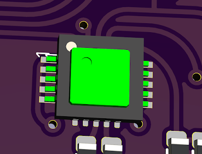
Update: I am also, as someone suggested, trying a CH340X which is physically a similar size for the FT231XQ but a lot cheaper and simper to wire up.
 |
| Superimposed CH340X (green) on FT231XQ |
 |
| Design for USB-A ESP32-PICO-MINI-02 with RGB LED and CH340X |
Update: Fuck sake, read the data sheet. 4k7 from CTR to DTR/TNOW is needed, not 4k7 from 3V3 to DTR/TNOW. Sadly meant some boards could not even be reworked. But was able to test this for future boards.


I've seen people do similar and slightly offset the holes in a zig zag pattern to add a bit more friction to hold the pins
ReplyDeleteIndeed, I have been pondering that as well. Maybe next iteration :-)
DeleteYou may want to look at pogo pins? But the advanced USB capabilities on the S2/S3 series make the jump well worthwhile, bye bye serial converters, Hello mass USB storage config files!
ReplyDeleteNice board. Interestingly, Amazon are offering same day delivery to me in Manchester at the time of writing when I've only ever seen that on more mainstream items.
ReplyDelete