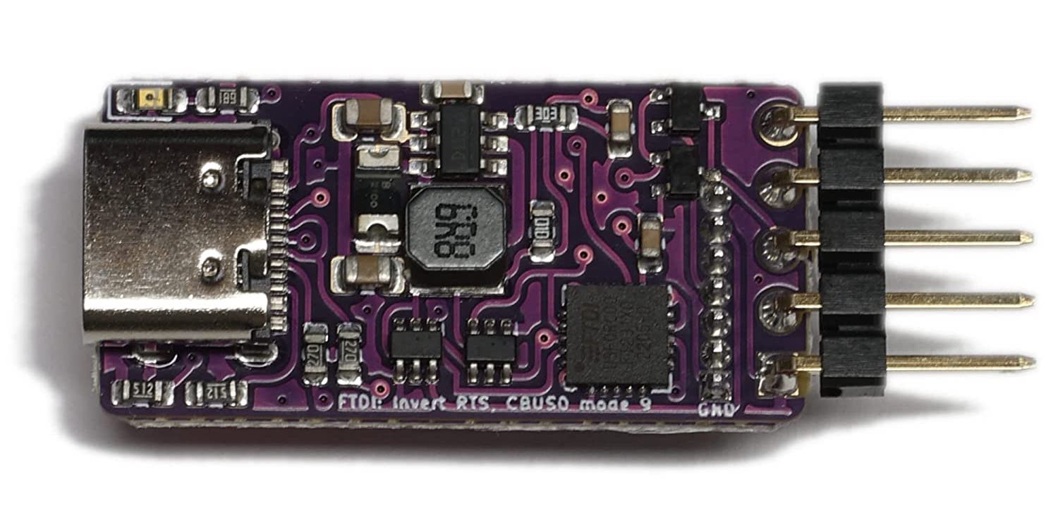
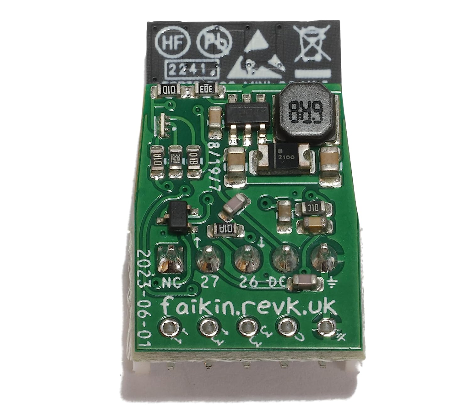
The CH340X is a small chip that does USB UART, and is part of a family of CH340 chips in various sizes. A UART can need few or many pins, and they do a really small one that is just Rx, Tx and RTS pins, which is the minimum you would want. But they also do a version specially aimed at the needs of small processors like the ESP to handle boot mode.

BOOT and RESET
Both ESP8266 and ESP32 (and many other processors) have a BOOT and RESET input, well, actually GPIO0 and EN.
You need these to program and debug. To program you have to set BOOT MODE, (which is GPIO0 pulled low) and pulse RESET (EN low and then high). For debug, you want no BOOT or RESET, or maybe RESET to restart the processor, but not BOOT mode (GPIO0 staying high).
What is weird is the various ESP based modules out there. I have seen complicated FET based links of RTS and DTR from a UART linked to GPIO0 and EN, and some with R/C combinations linked to RST and GPIO0. I think the logic here is for more traditional use of DTR and RTS, i.e. usually one has RTS active the whole time, so an R/C allows RTS to be activated (low) but EN to pulse low and back high. Similarly linking the use of DTR and RTS to allow a normal UART operation not to be BOOT MODE.
However, the esptool and idf.py as part of the ESP IDF, and even the tasmotizer tool and web page all treat DTR as BOOT MODE and RTS as RESET directly.
You can connect DTR directly to GPIO0 and RTS directly to EN, and it works perfectly!
What is even more weird is the number of modules you see with actual push buttons for BOOT and RESET on the board, which costs money to fit, even though they have a USB UART.
I can only assume some legacy designs and copying reference designs and so on.
All my designs connect DTR to GPIO0 and RST to EN, and work perfectly. Yay.
CH340X DTR
The CH340X has Tx and Rx and also CTS (input) and DTR/TNOW (output).
The TNOW is multi function though, the datasheet says :-
5.3. DTR and multi-mode MCU download
For CH340X, 6# Pin defaults to TNOW, weak pull-up during power-on or reset, output TNOW during normal operation used for half-duplex transceiver switchover. By connecting an external resistor with 6# pin, TNOW can be switch to DTR#, the two options are as follows:
1 If the 4.7KΩ pull-down resistor is connected to GND with the 6# pin, it will enter the open source DTR enhanced mode, and the 6# pin will automatically switch to the open source driven DTR# pin , which is used to connect the boot mode pin of MCU. The default DTR # is not output and is kept low by the external resistor, but the DTR# pin can be set to output high level or not output by the application program, which is used for multi-mode MCU download with DTR# default low level.
2 If a 4.7KΩ resistor is connected between the 6# pin and the 5# pin, it will enter the push-pull DTR enhanced mode, and the 6# pin will automatically switch to the push-pull driven DTR# for connecting to
the control pin of the MCU. The application program sets the DTR# pin to output high or low level for multi-mode MCU download with DTR# default high level.
This is excellent, and makes it clear they have considered the use of DTR as a BOOT MODE for processors. I have not tested the DTR to GND via 4k7 - I think they are saying it inverts, i.e. DTR drives high. I may be wrong.
But the second mode, DTR to CTS via 4k7, I have tested. Well, actually I misread / assumed 4k7 to 3.3V, and that does not work, but when 4k7 to CTS it works, and drives the pin as DTR allowing direct connect to GPIO0 yay
Why a 4k7?
But I am puzzled. I understand the 4k7 to GND, as it pulls down, and allows active drive high as needed. But why 4k7 to CTS.
CTS is an input, so the only use of the link is to allow the CH340 to confirm the connection from DTR/TNOW (output) to CTS (input). Indeed, it pulses that output low a few milliseconds after startup, presumably to test it is connected to CTS.
The thing that puzzles me is why the 4k7. With CTS as an input it is quite safe and valid to connect DTR directly to CTS, output to input. And, as you would expect, doing that causes the CH340X to switch in to DTR output mode.
I suppose one could argue that you may want to make use of CTS as well, and the 4k7 allows that even if DTR is outputting something different. Except that does not work. If you are using CTS, that means you have an active signal feeding CTS from somewhere. If that is the case, the test of DTR to CTS does not work (I tried it!) as CTS will not see the signal from DTR/TNOW via the 4k7. So the 4k7 does not allow that. Indeed, the only use may be if you have something driving CTS which does not drive it at power up - that would be a rather special arrangement and somewhat unlikely. That said, I suppose if CTS was a general purpose GPIO from a CPU which starts as floating/input, it could make sense and allow CTS to be signalled from the CPU.
So I'd expect the data sheet to say just link DTR to CTS and not use CTS, or use 4k7 if CTS is floating at power up and needs to be used.
Anyway I have done that (just linked DTR to CTS), and it works nicely.
 |
| USB-A tracks to CH340X |
There is a snag though - using DTR to drive GPIO0 works, but on my Shelly board it is drive GPIO0 that is connected internally in the board, with some pull something, and an LED, and so on. So the CH340 might "see" the pull down on it when it starts perhaps. So I have to drive through a buffer in that case. Thankfully that is basically the only case, as normally it just goes directly to GPIO0 on the connected ESP module.