Showing posts with label ESP32. Show all posts

2025-06-01

Infra-red remote conrols

I have done a lot of stuff over the years, and the "old" tech, like barcodes, and modems, faxes, and all sorts have not passed me by, even old school "light pen" on a BBC micro.

But somehow one "old" tech passed me by somehow, and I am not sure how - the IR Remote.

They are a lot like barcodes, but without the variable timings. They are simple, and why the hell, in the last 50 years, have I never played with IR remotes? Mad.

So I have started.

This is my environmental board, and apart from light, sound, pressure, temp, humidity and CO₂ sensors, it has an IR receiver. So I had a play.

The ESP32 has built in IR receiver (RMT) hardware that logs timings for the on/off from the IR receiver modules (which handles the 38kHz modulation for me).

It is a doddle to decode - actually way easier than barcodes. So I have decoded the very common NEC format, and the remote for the Daikin air-con.

NEC

The NEC coding is simple - a long/short header, and then pulse distance coding of 32 bits. It is 4 bytes (and annoyingly low bit first) which are address, and inverted address, and code, and inverted code, making a checked 16 bit sequence of fixed time duration.

This seems to cover a variety of bog standards remotes, like TV remotes. Interestingly my LG TV remote only does IR when the TV is off. Once on, it uses something else (not sure if bluetooth or what). It uses address 04.

I also have a very generic IR remote from Amazon, which is address code 00, and several (very illogically mapped) codes.

A single bit code 0, with a different timing header burst, is repeated whilst the button is pressed. Easy to decode press, hold, release.

Daikin

The Daikin remote is more complex, some 8 byte sequences, and a 19 bytes sequence, sent every time, using a simple byte checksum code at the end. Again, pulse distance coding. But again not hard to decode.

More

I have some more IR remotes coming to play with. So we'll see how they work.

2025-05-22

Evolution of my code and PCBs

One the last few weeks my code and PCB designs have evolved a bit!

EPD

This is still called EPD (E-Paper Display), but in practice it is now a general purpose signage system allowing a number of widgets to be displayed getting data from many sources. Making it work with the 2" and 2.4" waveshare LCDs was nice. I got my PNG code doing colour nicely for this, and alpha blending.

One aspect I was very pleased about was the display connection - the display has 8 pads/holes at 0.1" spacing for a normal 0.1" header pin strip. Making a board to work with this is easy and you solder top and bottom - done! But it makes it almost impossible to remove cleanly if ever needed.


The trick is a surface mount header on my board, on top of pads/holes to allow for longer pins. This then allows 0.1" header pins on the display that then just plug in. It can be unplugged simply if access needed for connectors, or if changing display/board at any point. 

But the code has evolved even more - allowing a wide number of sensors (I2C and one-wire-bus), and formatting specially for temperatures (small C/F, colour based on range), etc. And now even BLE based temperature and humidity sensors as well.

In fact, with all of the sensors reporting to Home Assistant, I have had to make a "non display" version of the code for someone that is using this with no display - which is crazy for code designed to display stuff.

I also added handing of buttons as the board (see below) has them, causing Home Assistant triggers.

Faikin Remote

This other code has worked very much in parallel with a lot in common - including adding a load of sensors, the same as EPD. The main use case is to work a Faikin.

However the PCB design for this has ended up being a key module for use with my EPD code. It too has changed.

The initial sensors were temperature (as main thing for Faikin remote), humidity, and CO₂. The module is designed to also work a fan and radiator based - fan based on humidity and CO₂, and radiator based on temperature for cases where you have air-con and radiator. But it works for rooms I have that only have radiator, obviously. So it is an environmental monitor (working with HA) and a remote for the Faikin.

It also has pressure, so the CO₂ can be calibrated, and a light sensor so it can go off when dark (ideal for a bedroom).

But it is growing, with my latest designs (not yet on sale) having a microphone for noise level, and also an IR remote receiver. The idea of the IR is that a Daikin remote could work this directly. I'll need to code these soon.

It is becoming a really comprehensive environmental monitoring board now.

I was also asked to make the snap off bits (button, CO₂, and now IR) have pads to allow them to be wired in, so that is done - you can remove and mount nearby and wire back to the board.

Practical uses

Obviously I have these working with Faikin modules, and have them working with radiators (with and without air-con), and in places just monitoring. Some customers have them around offices to monitor workspace environmental conditions.

One good use case with remote BLE sensors is the pub. Showing BLE sensors in various places, and the DS18B20 temperature probe from another of the boards in the cellar monitoring the beer cooler. The fact this is all visible from the bar now makes life easier, and highlights any out of temperature readings (like when someone opened the beer keg store room to put in a sensor).

What is ideal is this is all reported and logged and graphed on Home Assistant as well. Any issues with the beer/lager the bar staff can see if there is an issue with the cooler at a glance (as had happened a couple of times). We also have logs and graphs which helps when the engineer comes in to sort the cooler.

Next step is probably one monitoring all the fridges. I found these small BLE sensors manage to work inside a metal fridge, if you are close enough. They will still do their temp checks, but this will alert quickly in one place if any issues, and provide historical records nicely. Obviously we check these with a calibrated thermometer as well.

All I need to do now is find a source of the BLE sensors that still work and can be flashed with Telink Flasher. Any pointers welcome.

Tindie

Yes, the code and PCB design is all open source, and I have these on Tindie. I do a tad cheaper for collection from Aber if you are local. Check it out as there is quite a lot on there now.

2025-02-25

Confidence

This is one of those more personal blogs.

This week, well, started last week, I had a small technical challenge. The exact details do not really matter for this. But I'll explain.

I wanted to code something - something that was not quite readily available (some people had things very close to something I could just use, but not quite, which is where it gets fun).

The boring bit: It was a system to decode PNG image files, and allow me to use them in an embedded system driving a e-paper display. The details do not matter.

All that matters is that it was not easy to do - it involved understanding a detailed technical specification (PNG), and a new thing (zlib) which I had not used before. For a change the specification is a really really good one, which, in many ways, makes it easier.

Can I do it at all?

A biggie for me is should I, can I, even embark on this project.

To be clear, I have no reason to. Nobody wants this (well they may now), nobody needs this, nobody is asking for this, nobody is paying me for this. It is solely to make an e-paper thing I have easier to use. It is educational for me, a challenge.

Indeed, many of the helpful suggestions are to use a different file format, and not png. I do that already, but I wanted to make it simple - all can handle "save as png" I feel, so can I make it handle png. All and every format for png though?!

The protocol - the file format, which I literally sat in hot tub for over two hours reading, is good. But has some tricky bits. One is the compression/expansion using zlib, something I have never done.

I was seriously concerned I could make this work at all. Could I do it? Could I do it in a way that fitted in memory on an ESP32? Am I up to the job?

Yes I can!

I decided to go for it, in linux and then ESP32 code.

Each step worked well, and was not an issue. Minor changes as I coded. Lots of testing. zlib is easy, it turns out. zlib works on ESP32 too.

PNG has a lot of options, and as a decoder you have to handle them all. As an encoder you can be picky, but decoders cannot. I had to slog over the different options - make every one work properly.

In a day?

I spent a day, well, until early afternoon, and then a couple of hours next day. Total time under one day's work.

It works!

It went perfectly - the bugs were simple to fix. When I slept on it, all the remaining bugs came to me in my sleep, like they used to.

Not lost it?

So no, I have not lost it!

The work was not as easy as it used to be - younger me would have worked on in that evening and not next day. Younger me would not have made as many typos (way more since I had a stroke). But the results is good.

I worry about "losing it", and "imposter syndrome" all the time. I hope this is is a good sign I am not a losing the plot, honest.

Here it is https://github.com/revk/ESP32-LWPNG

2025-02-09

IronMan

The IronMan project has been challenging...

Basically, we know someone that does IronMan for events and parties, along with others that do Spiderman, and so on.

But the suit he has is somewhat failing - the original electronics failed a long time ago, and the reworks (no idea who did) also failed.

So this is at least third, or more, refit for this, but we have taken it on with some serious dedication I think.

The helmet

The helmet has a servo, to lift the visor, and LEDs for the eyes. We actually replaced the electronics on this twice - initially a simple LED controller, and then a more custom board.

The eyes are now WS2812 LED strips. so way more flexible, even if normally just static cyan.

One of the challenges was the current spikes from the servo - it killed LEDs. Big capacitors is the main fix for this.

The suit

The suit was also a challenge, and really, the stuff in there was a mess. Again, two stages, firstly a simple LED controller for the "arc reactor", but now gutting it all and replacing with custom controller handling multiple LED strips, and speakers.

The previous electronics had several primary cells, a rechargeable battery, and speakers and LEDs. But the speakers never worked properly apparently.

The new build takes a lot less space, is rechargeable, and lasts all day.

The gloves

These were especially challenging. The helmet and suit could accommodate a decent USB battery pack. But the glove are too small, so needed a design that could handle a small LiPo, and charging.

The previous electronics were a simple LED torch fitting and 9V primary cell. This was bulky, and just "lit up".

The new design is a rechargeable LiPo, and 88 RGB LED rings with diffuser, button, and repulsor effect.

Overall

The end result is nothing short of as complete revamp.

Less space taken in helmet, gloves, and suit. Rechargeable batteries in all, all lasting 8 hours. BLE linking so sound effects link to repulsor in gloves and helmet sounds.

At this stage there is concern the LEDs for the arc reactor and gloves may be too bright, and the speakers too loud, both of which can easily be adjusted.

Speakers

One of my concerns was the speakers, and I found these were the best. I tried 5 different types.

From PiHut, and really good.

They are glued inside the suit but sound awesome.

My son should have a video on it all soon.

2024-12-17

ESP32 SD Card wiring and driving

This is so that people like me find it and know what I learned.

Making an ESP32 board with Micro SD slot, in my case specifically an ESP32-S3

First step, wiring up. This is what I have ended up with.

There were other stages, including just the pins you need for SPI mode, which mean no SDDAT1 or SDDAT2 lines. But with them having a pull up anyway. For SPI they have different meanings and labels, typically. The other stage was no resistors.

Resistors or not?

This is complicated, honest. After lots of reading of all sorts of pages and comments it seems...

  • The resistors are part of the spec, so highly recommended.
  • The resistors are needed for the default, old school, initial (slow) mode by which SD cards work as they use open drain driving (pulling down only) and need resistors to return signal back up. But, you don't stay in that mode - you switch to a mode where pins are driven both ways, so why does it matter?
  • Some cards even have internal resistors, it seems. But no ideal which. So some may "just work" anyway.
  • The ESP32 has an option of pull up resistors, but these take time to rise, and so do not work well if you have no resistors - the practical impact is really slow data transfer (using SPI mode) - but otherwise working. You can actually work around this with driving the CS in SPI mode low rather that using the library, it seems, at least for SPI mode working.
  • The resistors also help avoid odd power usage on floating pins even if not being used, but again, you change mode to one that does not use open drain.

End result, just simpler to have the resistors, even if that means squeezing them in on a small PCB.

GPIOs

This is 7 GPIOs, a lot, but they can be mapped to adjacent pins, and the right order, to connect directly to the Micro SD card slot. SPI mode could use only 5 if needed, but best to have all the pull ups anyway.

SPI or MMC control libraries

Lots of examples of SPI wiring and SPI drivers, leaving some NC pins or leaving them with just pull ups. This is what I started with. But it was not as fast as I wanted (reading and writing around 250kB/sec).

It seems the MMC drivers are way faster, simpler as that, even when using 1 bit. I now have boards coming with 4 bit working to compare. With one bit I am writing 350kB/s and reading 750kB/sec, so may be the specific SD card is slow - more tests needed, and will be interesting to see 4 bit mode -  I'll update this post.

2023-11-28

No No-bell prize

I wanted to improve our doorbell... Yes, that is dull.

But the main change is not the bell (a nice, old style bell in the kitchen, which is driven by a Shelly, and the sitting room, and flashing lights in bedrooms and hot tub), or the bell push itself as such, but a sign on the door by the bell.

We used to have a simple brass "please ring the bell" sign, pointing to the bell push. Still, too many people knock instead.

Push the button

So the idea is a sign, and additional bell push right by it, on the actual door. The sign has the house name and number and road name - that itself may help as we get parcels for the same number in the next road often, and they get ours. But a sign saying ring the bell with a hand pointing to the bell push right by the sign.

The magic happens when they push the bell (either the new or old bell push) - the sign lights LEDs on the back and changes. The basic option is like this...

I included a barcode with date time and postcode for photos when leaving a parcel.

Seasons greetings

I also decided it may be a fun idea to change the message, add Christmas tree for now, and so on, but even regionalise the message...


The idle message can be updated and made seasonal, I may even automate based on date, but also the message shown when you press the button can vary depending on circumstances. This saves me putting a sign on the door when we are out - which is a notice to everyone that we are, well, out. The message for when we are out ("leave parcels behind the double gates") is only shown when someone pushes the bell. Indeed other messages can be set if needed.

Let there be light

The main way it decides what to show is based on lights. Yes, that seems crazy, but is incredibly simple when almost all lights are Shelly running tasmota and reporting to MQTT. I can track light states. I have a stairs light which only gets turned off when the alarm is set (we are out). I also track the hall light, which is an easy way I can indicate "we are busy, leave by the door" for when I am in the hot tub, etc. Indeed, if I change a light when the message shown updates in real time, so if in the hot tub I can remote turn off the hall light from my phone when the bell rings.

I also have Mastodon DMs for the bell, with exact time stamps to make easy to find in CCTV.

It also means control of the status display is something my wife can also easily understand and change if she wants, just using light switches.

Making a board

Obviously I designed my own circuit board for this. It works with a waveshare 7.5" e-paper display.


It sticks to the back of the board, has an ESP32-S3 with wifi, USB connectors, and big solder tabs for wires for power and the bell itself. It was designed so it could be set in resin even (though that seems to break the e-paper, possibly by getting in the FPC connector). So a bare board with acrylic spray for now.

No-bell prize

It did not work. The screen did not update properly. I was disappointed to say the least.

Old
New

The fix was to change the inductor and make it work, yay, no no-bell prize for me now.

So, finally, it works!

Update: The only reason this board is this size is because it has LEDs (one in each corner) do fits the 7.5" e-paper. If not then it could use a much smaller board, which I have also designed. But the new version of this larger board now has 24 LEDs, given that the LEDs are the only reason for the larger board this makes sense, but it may be a slight power issue as they are 10mA when white, so some testing may be necessary.

Update: I love the fact I have been accused of "nerd sniping" Bloor. He got one of these 7.5" panels with the waveshare HAT, and somehow he totally messed up the simple task of the FPC connectors, so much he broke several of them, and then managed to crack the display trying to get one working, and threw it all away. I come in and not only have no problem with the connectors, but then I don't just use the 7.5" panel and HAT with no problem, but make my own better PCB, and a new smaller PCB, and a version 2 of both boards, and a working door sign, and now even listing on Amazon! Is that "nerd sniping", or am I bad?

2023-11-01

LiPo batteries

I have done a lot of small circuit boards, but one of the challenges with any board is battery working.

I used the Watchy as a good example of this, understanding how to put the ESP32 in to deep sleep and so on. This worked very well. What I had not done until now was actually make a battery based board myself.

The first attempt, which was a massive long shot, was to test if I could run an ESP32 (ESP32-S3-MINI-1) off a button cell. The answer is no. This was not a big surprise.

So the next attempt was this :-

This has a small LiPo battery, an LDO regulator, and a charger circuit. This is basically copied the choice of components for these from the Watchy design.

There are a few things you need for battery working though - for a start, I have a FET to control power to the LED chain. The LEDs, when idle, do use very little power, but for battery working I want it to be zero power. So I have a GPIO that actually switches the power for the LED chain on and off (this is the small WS2812B compatible 3.3V RGB LEDs I have been using lately).

Another small trick is to also use a FET to switch the battery voltage to an ADC. The ADC on the ESP32 needs a lower voltage, so has a potential divider. The problem is a potential divider uses a small amount of current all the time - so again, this is switched on using a FET. I don't know if that is really necessary, but every uA helps. This should, hopefully, allow me to confirm battery levels whenever I need.

One small issue, which I have yet to quite get to the bottom of, is waking from deep sleep. The ESP32 IDF seems to suggest it is possible to make any RTC GPIO cause a wake on a state change. This is ideal for any buttons (I have two on that board design). However, that did not seem to work. I'll experiment more. There is, however, a separate way to do this, which is you can have a set of RTC GPIOs and wake on "any high" or "all low". For more than one button (I added two for the hell of it), this only really works if you have the idle state of the button low, not high. I had, as is common, had these buttons switched to GND with a pull up. I had to change the design not be reversed to allow wake on either button being pressed (at least until I get the "change of state" logic working).

I had fun finding a suitable upright USB-C connector, and I have juggled the various connector positions a bit since this original design.

Now to find what the battery life is when idle, and how many times you can use it before it goes flat. But it does work - yay!

2023-08-11

ESP32-S3-MINI-1 GPIO

I now have a few boards, including a general test board...

The ESP32-S3-MINI-1 has 39 GPIO pins, though the data sheet defines that one (GPIO26) is reserved when using PSRAM (e.g. ESP32-S3-MINI-1-N4R2).

Unlike the S1 boards, the GPIO are all available as input or output, making its very flexible. But as always there are some caveats on GPIO usage.

The following relates specifically to the ESP32-S3-MINI-1 module only.

Restricted use:

GPIO0

GPIO0 is the main strapping pin that defines BOOT mode. If low at startup the device enters boot mode. It is pulled up internally so can be left unconnected. This means you cannot use this as an input if there is any chance of the input being low at start up. It can be freely used as an output.

By far the most common usage for GPIO0 is connection to the cathode of a status LED.

GPIO19/20

By default these are USB. This may make them not ideal to use for inputs. Note that they can be configured not to be USB by a fuse setting, but will be USB on an unconfigured module. As such it is probably best to use for USB.

GPIO26

The cannot be used with a PSRAM module, e.g. ESP32-S3-MINI-1-N4R2. It can be used if not PSRAM, e.g. ESP32-S3-MINI-1-N8.

GPIO43/44

By default the boot serial console uses GPIO43 and GPIO44. This means GPIO43 is configured as an output at start up. There are settings to stop any actual output on this. This means it cannot be used as a driven input without at least a resistor to handle the clash at startup. GPIO44 is an input so can be used for any purpose without any problems generally.

GPIO46

GPIO46 only matters when in BOOT mode (GPIO0 low) and in such case must be low. It is pulled low by default so an be unconnected. But do not use this as an input that could be high at startup in BOOT mode. It can safely be used as an output.

Caution:

GPIO3

This is defined as a strapping pin, and is floating by default. However it is only relevant depending with some specific eFuse settings related to JTAG operation. When using the default USB JTAG working, this pin can be used as a general input or output.

GPIO45

GPIO46 impacts the voltage used for SPI, but depends on EFUSE_VDD_SPI_FORCE. But this efuse is already set by default on this module, which means GPIO45 is ignored. It can therefore be used as an input or output.

Serial or USB console?

The S3 modules have two ways you can operate the console - the normal serial (UART), and USB.

USB

The default USB working is as USB JTAG and Serial console. This allows flashing and debug console, and a lot more debugging using JTAG and OpenOCD. This is by far the simplest way to manage the module and what I would recommend.

In most cases my boards have USB, either a printed tab for USB-A or a USB-C connector, but in the rare cases they do not, it is simple to include a header for USB to work with a lead.

This nicely fits under the module itself, with no vias, so takes no space and so no component cost. I deliberately spaced as 0.1" header and with a polarity to avoid confusion.

Apart from using JTAG, the USB serial is not really serial, so is way quicker for flashing code than using the real serial port.

There is one small snag...

It is possible to use an efuse, and more importantly, it is possible for the application to turn off the USB pins. This can even be inadvertent (I have done this, loading code for a different board which had an LED on GPIO19). This then means you cannot use the USB port at all, so cannot reset or load code or anything.

For this one reason, it is always useful to have a fallback.

Serial

The other approach for flashing and console is the conventional serial port. For this you need to have at least Tx and Rx (GPIO43/44) pins, and boot mode (GPIO0), and a means to reset (EN). You could use power on as the reset and keep it to just 5 pins. I use a header that works the same as the Shelly 1 and so can use my Tasmotiser board.

This also fits under the processor rather nicely with no need for vias, and no component cost. In fact, it can fit under the processor along with a USB header...

2023-08-08

ESP32-S3

I have worked through a few of these processors - starting with the ESP8266. I moved to the ESP32 quickly and have not looked back - initially with the WROOM module (which can be hand soldered), to the PICO module (which is smaller and needs solder stencil and paste).

But finally the ESP32-S3 (version 3 of the silicon) is available as a module, the ESP32-S3-MINI-1, so I am finally starting to use that. The fact that the ESP32-PICO-MINI seem to suddenly be out of stock, seems like the time to upgrade designs.

The S3 has several improvements which may be useful.

Size matters

A key difference is size. The ESP32-PICO-MINI (i.e. S1) is 13.2mm square plus antenna, but the ESP32-S3-MINI is 15.4mm square plus antenna. So 2.2mm wider and longer.

For almost all of my designs this slight change does not matter, and indeed, for some the other changes actually make things smaller. There are exceptions - the module to go in to the case of a Galaxy keypad may be too big as there is very little space.

However, there is one useful side effect of this extra size. I have a small 5 pad footprint for serial programming - it uses the same 5 pins as the Shelly, and is pretty much the minimum you can have for serial programming and debug (see on image above on the right of the components). Now the module is slightly bigger than can actually fit behind the module, so effectively taking no extra space on a single signed board. This is one of those small details that saves space - e.g. the design show above is now a couple of mm shorter as a result.

General purpose I/O

Another change is the GPIO. The S1 modules have fewer GPIO (27), but several of them are input only - all of one side of the module has no output GPIO. There are also a number of NC pins.

The S3 has more GPIO (39), and all of them are input and output. There are no NC pins (apart from GPIO26 when using the PSRAM based module). This means all three sides of the module have lots of usable GPIO. This is perfect for tracking as you can easily track to the nearest convenient GPIO, which saves space.

USB

This is where it gets both interesting and slightly disappointing.

The S3 has USB built in, so direct connection of D- and D+ pins to specific GPIO. It can be disabled, and it can be used in s/w as USB server or client side as needed, which is very cool. This saves space on many designs if no UART needed.

The default, starting point, is USB JTAG with USB serial. This appears on my Mac, for a totally un-programmed module, as a USB serial port. I can connect to it and see the boot loader serial output. This is excellent as it means I can use a much simpler interface to the module - no need for a UART. As many of my modules have USB for programming and debug, this makes it a lot simpler.

However, there is a snag, it seems. Whilst this works as you would expect as a serial console port over USB, it seems it does not provide the normal connection for RST to reset, and DTR to boot mode (GPIO0). So you can only really use it to load code if you have a button for GPIO0 and RST on your board. This is a lot of board space, and really is silly.

 UPDATE: I don't know what was wrong with my first test boards, but this is working, so, all OK! I think perhaps I simply had out of date tools on my Mac (e.g. esptool).

Now, there are a few rays of sunshine.

  1. It seems when un-programmed it does work in boot mode and so can be flashed, even though no RST or DTR working. That said, it seemed oddly intermittent, so I plan to do more testing on that. It may mean I can use USB for the initial loading of code and fuse settings.
  2. Obviously as a USB JTAG interface it may be that there are ways to force a reset and boot mode or load code over JTAG, but this is not obvious from the documentation. If I can work that out I can make boards which do not also need my 5 pad serial header, which is what I was aiming for.
  3. It is possible to internally detach this USB JTAG/serial and run USB from code in the module - this can handle code loading as a feature you compile in it seems (though even that suggests GPIO0 needed - why?!). I have not sorted that yet. My main concern is that if the code in the module does not have this, or is crashing, or whatever, I will have no fall back unless I have my serial header.

So more to do, and any help welcome. If there is a fallback for the USB JTAG working that allows code loading without having to do GPIO0 and reset, that would be really nice. For now, I'll keep my 5 pad serial, under the chip itself, as a fallback.

In theory OpenOCD is loaded, and should work for the JTAG. No idea how to use that yet, but that is a different matter as it does not work - some obscure error which sounds like a libusb issue on modern Macs. Arg!

Security

One small concern - JTAG is usually a very powerful interface on a system. If the chip is left with USB JTAG set up, perhaps because that is the only way to load code sensibly, it may also mean it can be controlled such as to allow secure boot and flash to be accessed. I.e. single stepping code after loading, etc. It may be that for security it needs the JTAG USB disabling (a one time e-fuse setting). I need to investigate. As a whole my security threat considerations have generally be based on physical access being a reasonable challenge, as the serial interface represents a similar risk in some cases, but it depends on the application.

2023-06-29

CH340X DTR/TNOW with ESP8266/ESP32 BOOT and RESET

The CH340X is a small chip that does USB UART, and is part of a family of CH340 chips in various sizes. A UART can need few or many pins, and they do a really small one that is just Rx, Tx and RTS pins, which is the minimum you would want. But they also do a version specially aimed at the needs of small processors like the ESP to handle boot mode.


BOOT and RESET

Both ESP8266 and ESP32 (and many other processors) have a BOOT and RESET input, well, actually GPIO0 and EN.

You need these to program and debug. To program you have to set BOOT MODE, (which is GPIO0 pulled low) and pulse RESET (EN low and then high). For debug, you want no BOOT or RESET, or maybe RESET to restart the processor, but not BOOT mode (GPIO0 staying high).

What is weird is the various ESP based modules out there. I have seen complicated FET based links of RTS and DTR from a UART linked to GPIO0 and EN, and some with R/C combinations linked to RST and GPIO0. I think the logic here is for more traditional use of DTR and RTS, i.e. usually one has RTS active the whole time, so an R/C allows RTS to be activated (low) but EN to pulse low and back high. Similarly linking the use of DTR and RTS to allow a normal UART operation not to be BOOT MODE.

However, the esptool and idf.py as part of the ESP IDF, and even the tasmotizer tool and web page all treat DTR as BOOT MODE and RTS as RESET directly.

You can connect DTR directly to GPIO0 and RTS directly to EN, and it works perfectly!

What is even more weird is the number of modules you see with actual push buttons for BOOT and RESET on the board, which costs money to fit, even though they have a USB UART.

I can only assume some legacy designs and copying reference designs and so on.

All my designs connect DTR to GPIO0 and RST to EN, and work perfectly. Yay.

CH340X DTR

The CH340X has Tx and Rx and also CTS (input) and DTR/TNOW (output).

The TNOW is multi function though, the datasheet says :-

5.3. DTR and multi-mode MCU download

For CH340X, 6# Pin defaults to TNOW, weak pull-up during power-on or reset, output TNOW during normal operation used for half-duplex transceiver switchover. By connecting an external resistor with 6# pin, TNOW can be switch to DTR#, the two options are as follows:

If the 4.7KΩ pull-down resistor is connected to GND with the 6# pin, it will enter the open source DTR enhanced mode, and the 6# pin will automatically switch to the open source driven DTR# pin , which is used to connect the boot mode pin of MCU. The default DTR # is not output and is kept low by the external resistor, but the DTR# pin can be set to output high level or not output by the application program, which is used for multi-mode MCU download with DTR# default low level.

If a 4.7KΩ resistor is connected between the 6# pin and the 5# pin, it will enter the push-pull DTR enhanced mode, and the 6# pin will automatically switch to the push-pull driven DTR# for connecting to

the control pin of the MCU. The application program sets the DTR# pin to output high or low level for multi-mode MCU download with DTR# default high level.

This is excellent, and makes it clear they have considered the use of DTR as a BOOT MODE for processors. I have not tested the DTR to GND via 4k7 - I think they are saying it inverts, i.e. DTR drives high. I may be wrong.

But the second mode, DTR to CTS via 4k7, I have tested. Well, actually I misread / assumed 4k7 to 3.3V, and that does not work, but when 4k7 to CTS it works, and drives the pin as DTR allowing direct connect to GPIO0 yay

Why a 4k7?

But I am puzzled. I understand the 4k7 to GND, as it pulls down, and allows active drive high as needed. But why 4k7 to CTS.

CTS is an input, so the only use of the link is to allow the CH340 to confirm the connection from DTR/TNOW (output) to CTS (input). Indeed, it pulses that output low a few milliseconds after startup, presumably to test it is connected to CTS.

The thing that puzzles me is why the 4k7. With CTS as an input it is quite safe and valid to connect DTR directly to CTS, output to input. And, as you would expect, doing that causes the CH340X to switch in to DTR output mode.

I suppose one could argue that you may want to make use of CTS as well, and the 4k7 allows that even if DTR is outputting something different. Except that does not work. If you are using CTS, that means you have an active signal feeding CTS from somewhere. If that is the case, the test of DTR to CTS does not work (I tried it!) as CTS will not see the signal from DTR/TNOW via the 4k7. So the 4k7 does not allow that. Indeed, the only use may be if you have something driving CTS which does not drive it at power up - that would be a rather special arrangement and somewhat unlikely. That said, I suppose if CTS was a general purpose GPIO from a CPU which starts as floating/input, it could make sense and allow CTS to be signalled from the CPU.

So I'd expect the data sheet to say just link DTR to CTS and not use CTS, or use 4k7 if CTS is floating at power up and needs to be used.

Anyway I have done that (just linked DTR to CTS), and it works nicely.

USB-A tracks to CH340X

There is a snag though - using DTR to drive GPIO0 works, but on my Shelly board it is drive GPIO0 that is connected internally in the board, with some pull something, and an LED, and so on. So the CH340 might "see" the pull down on it when it starts perhaps. So I have to drive through a buffer in that case. Thankfully that is basically the only case, as normally it just goes directly to GPIO0 on the connected ESP module.

2023-06-16

To USB or not to USB, that is the question!

I have done quite a lot of small boards now, as I have blogged at various points.

It has helped me build up my skills in circuit and PCB design, and over time I have moved to different approaches for things as I have learned. Some things driven by practical usage, some by cost, some by simplicity.

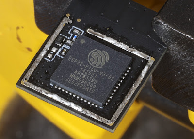
At present I am working on ESP32 based boards, and I may yet move on to ESP32-S2 or ESP32-S3, at least one of which does some direct USB, but for now, for ESP32, I need serial connection for programming and debug. The ESP32 are especially appealing in the form of the ESP32-PICO-MINI-02 module which has extra flash and RAM which is invaluable.

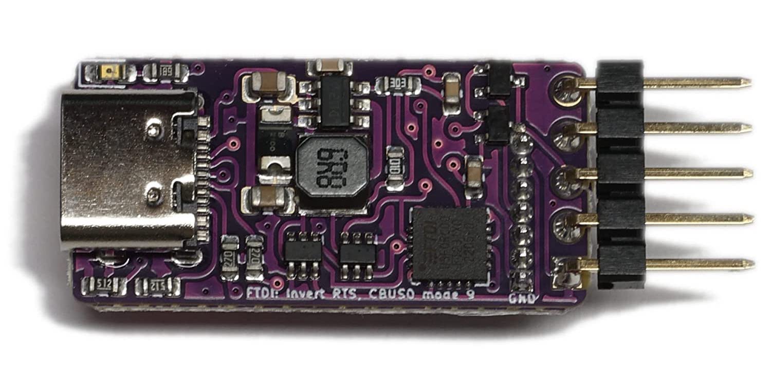
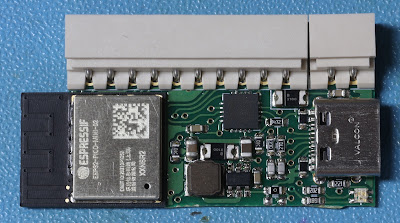
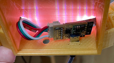
I have "standardised" on a USB-C connector for my boards, where needed, for simple power. That is most boards, e.g. this LED strip controller.

It uses USB-C for the 5V supply for the LED strip, and via 3.3V regulator for the ESP32.

In many designs, I have included an FT231XQ USB UART in the design, allowing not just power, but programming and debug via the USB-C connector. This works really well. It makes it very simple to develop on. I have even learned my lesson with diodes on boards which can also have 12V DC, and USB connecting both at the same time :-)

But the FT231XQ is not a cheap part, and not a readily available part (a lot of parts are now available after COVID, but some still in very short supply). So I have been making even these boards have an alternative for when the FT231XQ cannot be fitted.

Indeed, I have actually started making boards which have no FT231XQ at all, even if they have a USB-C socket for power (like the one shown above).

This means I need some sort of header. One of the reasons I went with the UART in the first place is any sort of sensible header connector would take as much board space as the UART chip, and add cost or time, especially if a through hole connector.

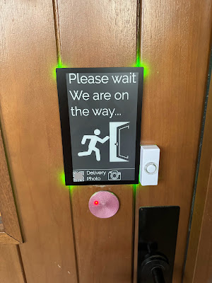
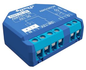
But, the way Shelly do it has come to the rescue. They use a small 1/10" 5 pin header (and a 1/20th" 7 pin header) - a socket on the board, and I made this to work with them. These are useful if you are wanting to reprogram Shelly with say tasmota, or for any projects with similar devices. See Amazon.

It has header pins for the 5 and 7 way connectors. The shelly has a proper socket for these.

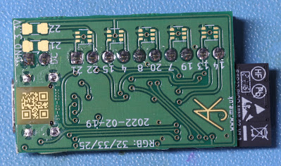
However, I can simply make the board have holes, instead of a proper "header", like the 5 holes on this boards.

I can simply push the pins in the holes, and hold them whilst programming. Indeed, if I can get the holes just right they will fit firmly enough not to need holding and so can be used for debug as well. It is cheap - holes don't really cost anything. It does not take a lot of space, especially as it can (like that example) be under another connector even.

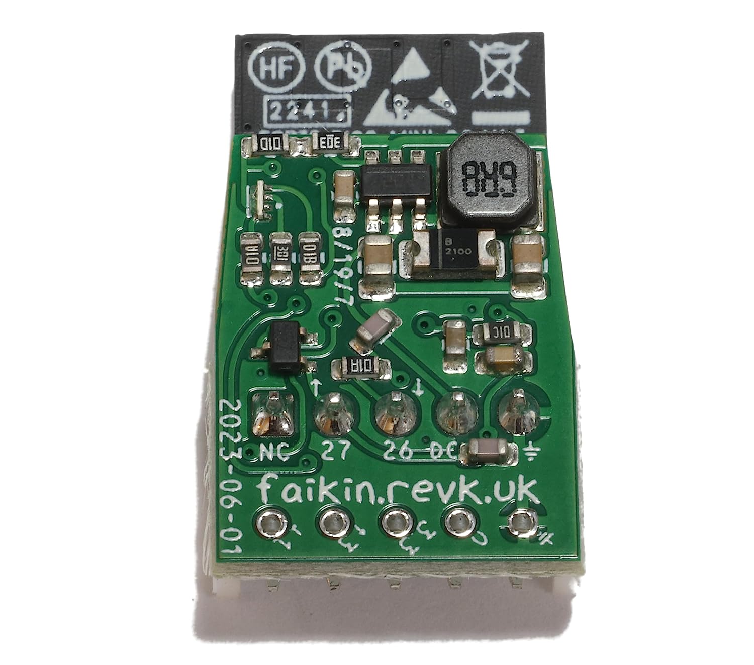
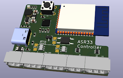
I am working on slight variations of the holes, to try and make a firm fit to the square pins. The latest is slotted holes. In practice this means each set of boards I get has a slight improvement and I try it. The above design had holes slightly too small - some boards needed to be "held" whilst programming (which is not really a problem, but adds some time). This is my latest design for them.

So it is a question of whether I bother with a UART on future boards. Using USB-C for power is a good idea for a lot of boards - the "Faikin" being one of the few cases where that is not sensible as it fits and existing connector with power. If I move to ESP32-S3 for example, I'll see if that can do USB sensibly directly, but I want a module like the ESP32-PICO-MINI-02 really - not sure if there is one yet.

Oh, and as you may notice, I have adopted a policy of GPIO numbers on silkscreen - it really is damn useful when you have so many generations of so many PCBs lying around. I don't do a lot of silk screen - i.e. no R1, R2, etc, but I have to do some to stop JLCPCB asking questions about pin 1. But GPIOs is invaluable. And now KiCad allows proper fonts it is slightly more fun (the above has "faikin.revk.uk" in xkcd script, err, because I can).

Update: As suggested (and as per above image) I have now gone for staggered pins, to see how that goes.

Update: The silk screen does not work that small, so going for something simpler...

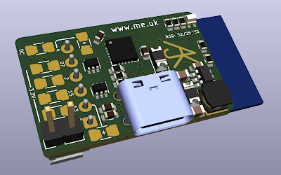
Update: I am also, as someone suggested, trying a CH340X which is physically a similar size for the FT231XQ but a lot cheaper and simper to wire up.

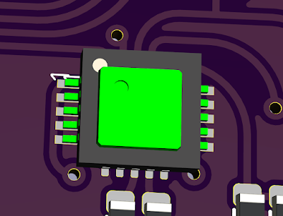
Superimposed CH340X (green) on FT231XQ

Design for USB-A ESP32-PICO-MINI-02 with RGB LED and CH340X

Update: Fuck sake, read the data sheet. 4k7 from CTR to DTR/TNOW is needed, not 4k7 from 3V3 to DTR/TNOW. Sadly meant some boards could not even be reworked. But was able to test this for future boards.

2023-05-30

SQFMI Watchy (first impressions)

I decided to get a Watchy to play with - mainly as a learning exercise, and I think for that it will be perfect. It was not that expensive (£48.80+VAT from Mouser, and free delivery). It comes as a kit which is very easy to assemble (probably because of the hassle of EMC, CE, UKCA, etc) but it is sold as a development device so not unreasonable, IMHO.

Hardware

The hardware is an ESP32, plastic case, rubber strap, battery, accelerometer, vibrator, real time clock chip, 4 buttons, a 200x200 e-paper display, USB connector, and battery charging circuit.

This is quite a nice set of hardware. My main concern is the e-paper display is not, in any way, protected, other than the recess in the case. I understand a screen protector may be available. As a watch it is slightly chunky, probably more than necessary. But it is nice. They have a milled aluminium case option as well.

Out of the box

Obviously it is a kit and needs assembly, which is very easy, but then it does work. However, I would have expected it to be a bit more slick to be honest. This has been around a few years now. Small details like...

  • Button pushes are not handled well, e.g. you can select an item in the menu and immediately have clicked the menu for the item - an example is Set Clock, which you have to press to select very briefly or you have skipped the "hour" and moved on to "minutes". Button response and handling could be a lot better. (Obviously the clock is ideally set by NTP over WIFi).
  • It lacks simple setting like time zone, even without DST, this seems like a setting a watch should have. It can be set, but by editing an include file in the code and re-flashing. The nicer default code also grabs weather but has a default city code set of New York, and you have to edit the include file to change that. A UI for that may be harder, but remember it has the option of serving a web page for more complex settings, so could handle this.
  • The 7 segment font is nice at full size but looks badly scaled down on smaller digits, which is a shame.
  • You expect to be able to upgrade the firmware, and there is an option. But the option says to go to a web site from bluetooth enabled phone, and click next. But the web site is the main page for Watchy and that has no hint of any tool for loading new code by any means. Why not have a simple WiFI OTA upgrade option?

P.S. I did not even consider, but for some, choice of 12 or 24 hour clock needs to be an option.

Trying some other code (examples)

Mouser say it works with Arduino, MicroPython, and ESP-IDF. The main reason to getting it was it works with ESP-IDF as that is what I use.

However, it seems it works with Arduino and PlatformIO. I see nothing on the web site about an ESP-IDF build environment.

I went for the simple option of loading Arduino. I don't like it, but it works, and the instructions were simple enough and only a few steps. It worked seamlessly to load new code, and that is where I found the include file for location and time zone and city.

There are a load of "example" watch faces, but they are all pretty crap. They are a fixed background and time in a different font. I mean there is one that looks like a DOS screen with time on the files listed. It is not good as a watch face really, but I see what they are getting at. But the others are all a similar theme, they just have time and maybe date in different font on a static image.

I would have hoped for something more interesting. Faces with sunrise/set, or moon phase, or an analogue face. But all the examples are boring. Now, I may well be missing a treasure trove of code somewhere on The Internet, but a poor impression to start with.

It would have made sense for the "standard" build to have a choice of "faces" as an option, all in the same code, even.

Learning exercise

As I say, the main reason is a learning exercise, so I hope to make my own code for this from scratch. This means e-paper drivers (I have done some before, so not hard), and accelerometer, and RTC, all of which should be simple. I can then make a nicer watch app for a start, I am sure. But not sure I would use as a watch. I know I have done a good job if one of the grand kids wants it when I am done. I was pondering showing solar production stats on it even.

But longer term there are a load of things I can learn using this as a test platform.

  • Ways to manage battery power, e.g. deep sleep until end of minute when updating time, and maybe the low power sub processor to check for button presses in between. That is all useful stuff to learn as they are features of the ESP32 and important for a lot of applications, not just a Watch.
  • Battery charging - I have not done battery based boards, but this has a battery and does charging. This is a good starting point to get my designs handling batteries sensibly.
  • Directly connected e-paper. I have played with e-paper but always as a "module", a display and board and some chips and a row of 0.1" connectors. This is directly e-paper to a connector on the board. This would be good to do on any design I have using e-paper. It makes it cheaper and smaller than using a module. So this gives me a way to do it (PCB wise) and a test platform.
  • Direct antenna. This uses the ESP32 chip directly with printed antenna. I have not dared do that myself. But if someone has done the work, I can copy what they did. It makes for less space and cheaper part and production than using the ESP32 modules. Definitely worth a try.
  • The accelerometer is not something I have touched before, so would be fun, but outside a watch I do not expect a use for it yet. The same is true of the RTC chip - they are generally quite simple.

Will I find the time?

This is perhaps more of a challenge. If I can get it off the ground with my own code, even just working the display, then I think I'll make a complete ESP-IDF based Watchy platform myself. I'll see how it goes.

Battery

And an update - I loaded the latest code and fully charged, and that was a week ago. It is still going. I am impressed, especially as it has been using WiFi to check weather to display and get NTP, regularly.

I am tempted to leave it until it stops. Being e-paper it should leave a time of death on its display in much the same way as an old mechanical watch in a murder mystery would do so, allowing a detective to prove the accurate time of death just after the medical examiner has got it wildly wrong.

Update: It lasted just under 3 weeks (20.5 days ish).

2022-08-17

Open the pod bay doors, HAL

I am pleased to say I finally have the locks sorted at home.

The underlying system is in use at the office and a number of other places, including a hackspace (whose feedback has been great), but as anyone that does software knows it really helps to actually be a user as well. I had the previous system at my previous house in Bracknell. But now in Wales, I wanted the new system as well. I like the system I have made, and using means I can more easily spot the improvements that are needed.

Several small tweaks over the last couple of months as installed. The locksmith has managed a reasonable job of this and coped with my wiring in the door quite well. The controller boards have got smaller and better over time.

It is a very different set up for domestic than for office, and that has been a challenge. The Abloy EL560 work well for this. We don't want "break glass" boxes and exit buttons, so needed some creative solutions to make it "wife approved" and secure at the same time.

My daughter, who is visiting this week, is the first person to have her door access card set up using multiple separate AIDs to allow use at the house here and the office in Bracknell, along with my grandson. The 8k DESFire cards allow this to work well with separate AIDs for each site to work independently.

Of course, said grandson, being far too inquisitive, especially near a hot soldering iron, is why my office door at home is currently default locked. Strangely enough this has led to an improvement today on reporting unauthorised access attempts. It reports all sorts of failures, bad fobs, even access outside time period, but straight up valid card that is "these are not the doors to which you have access, [waves hand]" was not flagged as obviously, and is now. Obviously he did not get access, but now, if he tries again, I get emails, and the teletype will go mental, and so on. LOL.

I should be doing another office soon as well, as a prototype. I really hope to be selling these soon - once component shortages are over (ha!). We'll put the modules on Amazon I expect.

2022-02-28

ESP32-PICO-MINI-02

I started playing with Espressif processors with the ESP8266, and quickly moved to the ESP32. The main module I have been using is the ESP32-WROOM-32. Using a module avoid having to mess with RF directly, and makes it a lot easier.

However, I have now discovered the new ESP32-PICO-MINI-02 module.

It is quite impressive.

  1. It is smaller, half the size of the ESP32-WROOM-32.
  2. It has more flash (8MB not 4MB, though WROOM modules can have more).
  3. It has SPI RAM (2MB) so a total of 2½MB RAM rather than just ½MB. Impressive.
  4. It cannot be hand soldered as pads underneath the module.
  5. Did I say it was tiny?

How is it so small? Well, unlike the ESP32-WROOM-32, which is several devices in the module (the processor and a flash), it is all one chip. They have integrated the flash and SPI RAM all in one device.

So, armed with this impressive new chip, I have been playing around with my various designs. Re-designing a board to use this is simple at the schematic level, but more of a challenge when it comes to layout. The good news is I am better at layout now, and doing a board a second time is easier, so I have managed to make all my various designs much smaller. This is quite helpful for things like the alarm system controller which has to fit in an EXIT button back box, and can be a squeeze, or even the Galaxy keypad controller than fits in a small gap in the case.

I have taken the chance to tidy up my designs a bit as well, lower power when not using USB, by turning off the USB controller, etc.

I have also designed to make some more boards - including a small generic module, using this:-

This provides 10 GPIO pins, but is a tiny board. I've also made a GPS board.

I was obviously a bit worried about a new module - did I read the data sheet right? Can I solder it (using solder paste) properly? Well I am pleased to say, it worked first time. Yay!

Update: The GPS module works as well. It is fun as has a few GPIOs not normally on the WROOM module (7, 8, and 20). It is worth noting that it uses an ESP32-PICO-V3-02 chip, the V3 and 02 all make slight differences, so worth checking data sheets carefully.

2022-01-30

More on KICad 6 and PCBs

I have been updating all my PCB designs to allow for using the more commonly available LMR16006 with variable voltage, rather than the fixed 3.3V regulator. All done now.

But I have also made a couple more boards.

For a start, an ESP32-WROOM-32 board with more GPIOs. The previous generic board was this.

It has 6 pins, GND plus 5xGPIO with some links. I have updated the silkscreen to have GPIO numbers all over the place as it is a pain to find them on older boards if not printed on the board!

But I decided a more powerful generic design may be in order, so did this new one today...

This is a tad bigger, but 16 GPIO pins. Yes, one each side is pre-linked to GND, but can be cut. And options to link to DC supply or 3.3V are always useful. Again, an RGB LED on board. And I have labelled all the GPIO numbers. This should be useful.

But this has been a busy weekend, and I have also made this...

Now this is a fun board, an interface for an ASR33 using 20mA current loop. It uses some simple ICs that are aimed at providing fixed current driver for LEDs, but seem ideal for this use. For avoidance of doubt this is not the same as 4-20mA current loop used for some control systems (an analogue signal level), but a simple make/break on 20mA, and used for teletypes 50+ years ago.

All of these will be a little over a week to arrive, so fun to test when they get here. I'll post more, specifically on the ASR33 board, once I have them.

To be honest I am amazed how easy KiCad makes it to just knock out a circuit design, do PCB layout, and be all ready to order actual boards.

2021-12-13

Dial the gate

One of the things I have not previously tried is LED strips/panels.

These are quite clever as they daisy chain one data line, allowing you to send colour data to every LED in a sequence, and hence make them all have any pattern you like. They are pretty quick too. There are a few chips out there, but Amazon have loads of strips and panels, such as a 1m/144 LED strip for £12 using WS2812B controllers.

Obviously libraries exist to make this easy to control. I use the ESP32 chips with the ESP-IDF development environment. However I am (for reasons too tedious to go in to) using CMake now instead of Make. I really do not know CMake well. So was fooled initially. Trying to include "led_strip.h" did not work.

It turned out that all I had to do was add "led_strip" to the CMakeLists.txt in COMPONENT_REQUIRES. And bingo. I am sure I tried that first, but must have got it wrong, but worked in the end.

It is then easy to use. Simple call to initialise, clear, set pixel colours, and flush out.

So what was the project? Well, I printed one of these from thingiverse. It is designed as a light. I struggled the thread the LED strip into it, and so I recommend printing 10% larger. I then wired directly to a USB powered ESP32 module, so 5V to the LED strip, and the 3.3V data line. To my surprise that works, as I was expecting to need to switch it to 5V data. Also, the LEDs can easily draw too much power causing USB to shut down, but by limiting the brightness (it was way too bright anyway) and using only 72 not 144 LEDs, I have kept it working. I just needed a bit of glue gun then.

This is the result :-)

The sequence is too fast for proper dialling, obviously, and it is spinning a blue LED not actually turning the ring. It lights in the chevron positions, but not the actual chevrons. But the bright light for the kwoosh, and then sparkly/fadey for the open gate, seem to work quite well. All on github.

It talks MQTT so I made it that when the house (electric) gates open, the gate opens in the living room :-)

That said, I also have a Shelly button1 lying around that does it too.

2021-11-20

ESP8266 vs ESP32

When I started using the Espressif processors I started with the ESP8266 and Arduino development platform. It is all C++ based (which is not really my favourite). But it is a really good starting point for anyone wanting to play around with microcontrollers.

One of the key things here is the available hardware. A "programming" lead is just a USB serial which is available for a few pounds, The Arduino development platform is free to download. But most importantly there are thousands of very cheap ESP8266 based devices on the market, easy to use, and many easy to access programming pins. The ESP8266 is possibly the most popular basis for IoT (Internet of Things) devices like smart light switches and the like.

However, having managed to make some PCBs (milled from copper boards) for ESP8266 based modules, I eventually decided to move on to using the ESP32. It had a number of advantages as a processor itself, but also the ESP IDF which works on linux and MacOS making it easy for me to code in C, which I prefer. The ESP IDF and various libraries are still a work in progress and far from perfect, but generally work well. I have made a load of projects based on ESP32.

But being ESP32 means I lack the thousands of ready made modules that I can use. I have designed and made loads of circuit boards myself, including a complete access control and alarm system.

What is now nice to see if that there are finally some ESP32 IoT devices coming out. Manufacturers are moving to ESP32 based boards. One of the most useful I have found is the Shelly 1. What is especially nice is it has direct pins for programming access - without even taking apart. It is simple, just a switch input and a relay output, but runs of mains, or 12V DC (do not use the GPIO pins when running on mains as they are live).

Shelly have just launched the Shelly plus 1, which is basically the same as the ESP8266 based Shelly 1 device, but ESP32 based. It also has programming pins easily accessible (though smaller), a relay and switch input. In this case the 12V is a screw terminal rather than a link you have to change.

The good news though is I can load my own code, ESP IDF based, on to this. It means I can use these modules directly on, say, my access control and alarm system. I had found I needed various simple 12V single input modules for the likes of a door contact or fire alarm input and previous used boards I made. But at this low price the Shelly plus 1 is a no brainer, as they say. Using my code I can set secure boot, and encrypted communications as part of the alarm system. Even something simple like an alarm bell could use one (single output for bell and single input for tamper).

My first actual project with one of these is for a servant bell system. I have an actual bell, which I want to "ding". I am using 12V DC, but the bell really only "rings" using AC. Using DC you need a small pulse to do a clean "ding". Too short and the clanger does not hit the bell. Too long and it hits it and holds, making more of a "clunk" than a "ding. Get it right and you get a nice clean "ding".

I was using tasmota32 code for this, but that is designed to do pulses of 200ms at least and not that consistent - perfect for blinking lights and the like, but no good for what I need.

So, back to my own code, ESP IDF based, using my existing libraries, and I am now starting something a bit like my own tasmota in a way - programmable inputs and outputs. Expect the outputs (which is all I have coded so far) are configurable to the millisecond.

I have found 15ms seems to be the sweet spot to make the bell ding...

2021-09-23

A use for the keypad

The Solar System alarm that I have created does work with a standard Honeywell Galaxy Mk7 keypad/display module.

However, until now, I have not really managed to work out a good use for how the keypad can be part of the system. But I have been working on that.

We now have clear display of inputs that trigger alarm, or inhibit setting, or faults, or tampers. We have setting the alarm, and unsetting using a PIN. Yay!

The way it all works is down to a small PCB, designed to fit inside the case of the display. It works off the same 12V supply, and provides RS485 to the keypad/display.


QR abuse...

I'm known for QR code stuff, and my library, but I have done some abuse of them for fun - I did round pixels  rather than rectangular, f...