Showing posts with label ESP IDF. Show all posts

2024-07-21

Bulk ESP32-S3 programming

Programming an ESP32-S3 is really easy.

The S3 has build in USB, which means literally just connecting GPIO 19 and 20 to D- and D+ on a USB socket - not even any resistors! It operates as a USB device out of the box, appearing as a serial/JTAG port. It just works on standard USB serial drivers on linux and MacOS (and I assume, Windows).

Using the ESP IDF tools I can type.

idf.py flash

And that is it, it detects the chip, and flashes the bootloader and code.

No special leads, it is that simple.

Smaller footprint

The only issue is that this all works if you have the complete ESP IDF installed, with its python and cross compiler environment, and your code checked out and built (or able to build). This is not hard, there are simple steps to do this, but it takes a lot of space.

So, I wanted something simpler so I could make a small machine, ideally a Raspberry Pi, that just flashed code. Thankfully, all I need is esptool, i.e.

pip install esptool

And then I can flash using that rather than the whole IDF. It is more complex, e.g.

esptool.py --chip esp32s3 -p /dev/ttyACM0 -b 460800 --before=default_reset --after=hard_reset write_flash --flash_mode dio --flash_freq 80m --flash_size keep 0x0 release/LED-S3-MINI-N4-R2-bootloader.bin 0x10000 release/LED-S3-MINI-N4-R2.bin 0x8000 release/LED-S3-MINI-N4-R2-partition-table.bin 0xd000 release/LED-S3-MINI-N4-R2-ota_data_initial.bin

But that is simple to script. One tool installed and the binaries from my repository, and job done!

One device after the next

The challenge is that I want to do bulk programming - i.e. flash a device, get clear confirmation it worked, then just plug in the next device. I don't want to run a command each time.

Getting confirmation it works is easy as all my boards have an LED, usually a tiny 1x1mm WS2812 colour LED, and that starts blinking as soon as the board starts. Indeed, the code is signed and checked on boot, so if any issues flashing it won't start.

Indeed, where I have done this I have had there separate instances running and 3 USB ports and leads, so I could plug in one after the other, unplugging when I see it is flashed and running. Really slick!

What I was doing was

idf.py flash monitor

This flashes, and then runs, and monitors serial output (which can be useful if there are additional diagnostics to show, but the main indicator is the on board LED).

The problem is you then have to kill the monitor for each board (ctrl ]). Even just disconnecting USB appears to wait for device to reconnect. I created a convoluted bit of C code to run monitor, and check output, looking for the string it gets for a new device, and exit. That way I could flash, and then run this, in a loop. Works well.

The problem is that, once again, this is using the whole ESP IDF just to run the idf.py command. And it seems esptool does not do a monitor function!

My own monitor code

In principle it is really easy to make my own C code to open the USB (serial) port directly, and set DTR and RTS appropriately to reset the board in running mode (rather than bootloader mode).

This worked perfectly on my Mac. Some simple code, waits for the right string to indicated a new board, and exits. It also does not need the whole ESP IDF to run.

But no!

  • The first issue is that the ESP32, with no code loaded, seemed to trip the power on the USB port. It is odd, and maybe the regulator I am using creates just enough of a power spike, or something (never bothered my Mac), I don't know. The fix was a powered USB hub.
  • The next issue is that once code is loaded, even with a powered USB hub, it seems the start up with WiFi is enough to then trip the power, so it constantly resets and does not blink the LED.
  • I finally found a power hub that just works with linux.

But there is weirder!

The other weirdness was that on the raspberry Pi, it seems it would not play properly with RTS and DTR and constantly came up in bootloader mode regardless. I simply could not get it to play, it was like DTR was not being set. The only difference seems to be it is using an OTG serial driver. On two separate bigger linux boxes, using a different driver, it works as expected (and ends up in a boot loop, as I said above).

I don't know how one can change the serial driver on a Pi, suggestions welcome (google did not help me).

2023-08-08

ESP32-S3

I have worked through a few of these processors - starting with the ESP8266. I moved to the ESP32 quickly and have not looked back - initially with the WROOM module (which can be hand soldered), to the PICO module (which is smaller and needs solder stencil and paste).

But finally the ESP32-S3 (version 3 of the silicon) is available as a module, the ESP32-S3-MINI-1, so I am finally starting to use that. The fact that the ESP32-PICO-MINI seem to suddenly be out of stock, seems like the time to upgrade designs.

The S3 has several improvements which may be useful.

Size matters

A key difference is size. The ESP32-PICO-MINI (i.e. S1) is 13.2mm square plus antenna, but the ESP32-S3-MINI is 15.4mm square plus antenna. So 2.2mm wider and longer.

For almost all of my designs this slight change does not matter, and indeed, for some the other changes actually make things smaller. There are exceptions - the module to go in to the case of a Galaxy keypad may be too big as there is very little space.

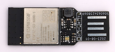
However, there is one useful side effect of this extra size. I have a small 5 pad footprint for serial programming - it uses the same 5 pins as the Shelly, and is pretty much the minimum you can have for serial programming and debug (see on image above on the right of the components). Now the module is slightly bigger than can actually fit behind the module, so effectively taking no extra space on a single signed board. This is one of those small details that saves space - e.g. the design show above is now a couple of mm shorter as a result.

General purpose I/O

Another change is the GPIO. The S1 modules have fewer GPIO (27), but several of them are input only - all of one side of the module has no output GPIO. There are also a number of NC pins.

The S3 has more GPIO (39), and all of them are input and output. There are no NC pins (apart from GPIO26 when using the PSRAM based module). This means all three sides of the module have lots of usable GPIO. This is perfect for tracking as you can easily track to the nearest convenient GPIO, which saves space.

USB

This is where it gets both interesting and slightly disappointing.

The S3 has USB built in, so direct connection of D- and D+ pins to specific GPIO. It can be disabled, and it can be used in s/w as USB server or client side as needed, which is very cool. This saves space on many designs if no UART needed.

The default, starting point, is USB JTAG with USB serial. This appears on my Mac, for a totally un-programmed module, as a USB serial port. I can connect to it and see the boot loader serial output. This is excellent as it means I can use a much simpler interface to the module - no need for a UART. As many of my modules have USB for programming and debug, this makes it a lot simpler.

However, there is a snag, it seems. Whilst this works as you would expect as a serial console port over USB, it seems it does not provide the normal connection for RST to reset, and DTR to boot mode (GPIO0). So you can only really use it to load code if you have a button for GPIO0 and RST on your board. This is a lot of board space, and really is silly.

 UPDATE: I don't know what was wrong with my first test boards, but this is working, so, all OK! I think perhaps I simply had out of date tools on my Mac (e.g. esptool).

Now, there are a few rays of sunshine.

  1. It seems when un-programmed it does work in boot mode and so can be flashed, even though no RST or DTR working. That said, it seemed oddly intermittent, so I plan to do more testing on that. It may mean I can use USB for the initial loading of code and fuse settings.
  2. Obviously as a USB JTAG interface it may be that there are ways to force a reset and boot mode or load code over JTAG, but this is not obvious from the documentation. If I can work that out I can make boards which do not also need my 5 pad serial header, which is what I was aiming for.
  3. It is possible to internally detach this USB JTAG/serial and run USB from code in the module - this can handle code loading as a feature you compile in it seems (though even that suggests GPIO0 needed - why?!). I have not sorted that yet. My main concern is that if the code in the module does not have this, or is crashing, or whatever, I will have no fall back unless I have my serial header.

So more to do, and any help welcome. If there is a fallback for the USB JTAG working that allows code loading without having to do GPIO0 and reset, that would be really nice. For now, I'll keep my 5 pad serial, under the chip itself, as a fallback.

In theory OpenOCD is loaded, and should work for the JTAG. No idea how to use that yet, but that is a different matter as it does not work - some obscure error which sounds like a libusb issue on modern Macs. Arg!

Security

One small concern - JTAG is usually a very powerful interface on a system. If the chip is left with USB JTAG set up, perhaps because that is the only way to load code sensibly, it may also mean it can be controlled such as to allow secure boot and flash to be accessed. I.e. single stepping code after loading, etc. It may be that for security it needs the JTAG USB disabling (a one time e-fuse setting). I need to investigate. As a whole my security threat considerations have generally be based on physical access being a reasonable challenge, as the serial interface represents a similar risk in some cases, but it depends on the application.

2021-11-20

ESP8266 vs ESP32

When I started using the Espressif processors I started with the ESP8266 and Arduino development platform. It is all C++ based (which is not really my favourite). But it is a really good starting point for anyone wanting to play around with microcontrollers.

One of the key things here is the available hardware. A "programming" lead is just a USB serial which is available for a few pounds, The Arduino development platform is free to download. But most importantly there are thousands of very cheap ESP8266 based devices on the market, easy to use, and many easy to access programming pins. The ESP8266 is possibly the most popular basis for IoT (Internet of Things) devices like smart light switches and the like.

However, having managed to make some PCBs (milled from copper boards) for ESP8266 based modules, I eventually decided to move on to using the ESP32. It had a number of advantages as a processor itself, but also the ESP IDF which works on linux and MacOS making it easy for me to code in C, which I prefer. The ESP IDF and various libraries are still a work in progress and far from perfect, but generally work well. I have made a load of projects based on ESP32.

But being ESP32 means I lack the thousands of ready made modules that I can use. I have designed and made loads of circuit boards myself, including a complete access control and alarm system.

What is now nice to see if that there are finally some ESP32 IoT devices coming out. Manufacturers are moving to ESP32 based boards. One of the most useful I have found is the Shelly 1. What is especially nice is it has direct pins for programming access - without even taking apart. It is simple, just a switch input and a relay output, but runs of mains, or 12V DC (do not use the GPIO pins when running on mains as they are live).

Shelly have just launched the Shelly plus 1, which is basically the same as the ESP8266 based Shelly 1 device, but ESP32 based. It also has programming pins easily accessible (though smaller), a relay and switch input. In this case the 12V is a screw terminal rather than a link you have to change.

The good news though is I can load my own code, ESP IDF based, on to this. It means I can use these modules directly on, say, my access control and alarm system. I had found I needed various simple 12V single input modules for the likes of a door contact or fire alarm input and previous used boards I made. But at this low price the Shelly plus 1 is a no brainer, as they say. Using my code I can set secure boot, and encrypted communications as part of the alarm system. Even something simple like an alarm bell could use one (single output for bell and single input for tamper).

My first actual project with one of these is for a servant bell system. I have an actual bell, which I want to "ding". I am using 12V DC, but the bell really only "rings" using AC. Using DC you need a small pulse to do a clean "ding". Too short and the clanger does not hit the bell. Too long and it hits it and holds, making more of a "clunk" than a "ding. Get it right and you get a nice clean "ding".

I was using tasmota32 code for this, but that is designed to do pulses of 200ms at least and not that consistent - perfect for blinking lights and the like, but no good for what I need.

So, back to my own code, ESP IDF based, using my existing libraries, and I am now starting something a bit like my own tasmota in a way - programmable inputs and outputs. Expect the outputs (which is all I have coded so far) are configurable to the millisecond.

I have found 15ms seems to be the sweet spot to make the bell ding...

QR abuse...

I'm known for QR code stuff, and my library, but I have done some abuse of them for fun - I did round pixels  rather than rectangular, f...