My first attempt as the RFID reader version of my "scales" system meant a lot of enamelled wire...
It was a tad messy, and time consuming. But worked well.
I decided a small PCB would be a better solution, and the answer for one-off PCBs is, of course, a milling machine.
Nearly 30 years ago I used such a machine when working at Nokia. It was very useful, and expensive. These days you can get a small CNC machine for under £200!
I purchased one from
Amazon (duh!).
It took some assembly, to say the least, but plenty of good
videos on line.
It has an arduino, which allows moving the head and running code (.nc) files from a micro SD card. It looks like the main machine talks serial / USB, but not got that playing just yet.
Making PCBs
I designed the PCB on inkscape, which is fine for a small PCB like this. The challenge, as always, is a small single sided PCB with minimal links. My first design assumed I could run tracks between the pins on a 0.1" header (which I could do 30 years ago). It seems this is tricky, to say the least. Maybe we can managed 1/20th" pitch devices like an SO8, just, but tracks between 0.1" headers are not so easy.
So I redesigned with "chunky" tracks. This meant one small link. A 1206 0Ω resistor would be ideal, and Amazon prime do them, but out of stock, so a wire will have to do.
In inscape it is easy to make tracks and pads. You then just stroke-to-path, and union the paths and tracks to make an SVG cut path. Of course this cuts on the track edge which makes the tracks smaller. You can make that a path and stroke-to-path again and union first stage, but that is faff. Simpler to design with chunky tracks and pads that almost touch when designing, knowing the cut path will be thicker. If that makes sense. Obvious I needed a layer for drilling, and cutting around the edge of the PCB, and the tracks.
Making GCODE
This is a lot harder than I expected - there seem to be several solutions, and FlatCAM looked promising, but I cannot get to work on my Mac. There is an svg2gcode tool, but did not work well. I ended up just making my own code to convert EPS to GCODE with options for speed and cut depth and so on. The GCODE goes on the SD card, and simple.
Stupid UI
The UI on the arduino is daft - it has a mode to control portion, but then uses all 8 buttons and has no way to
escape back to the main menu as far as I can see - so I set origin and have to power cycle to then run the file. Maybe I am being thick.
The result...
 |
| Milling |
 |
| Drilling |
 |
| Cutting |
Ok I cut too deep and cut in to the bed, idiot. I'll either cut less or add a sacrificial layer below.
 |
| That worked |
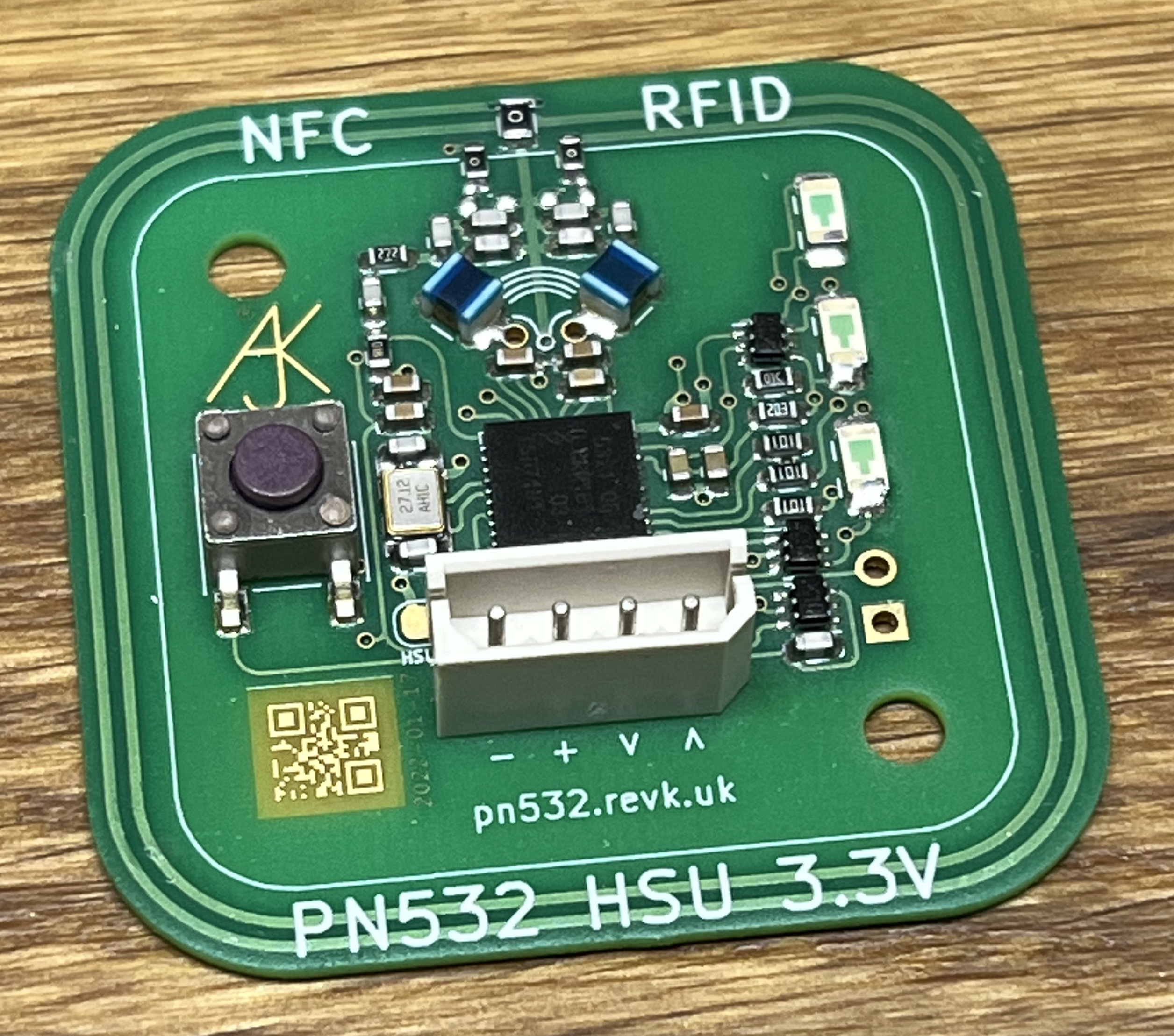
Final PCB
It is not that good, but the design with chunky tracks means it works!
And time to try it out for real...
It only bloody works!!!
P.S. I have open sourced the eps2gcode.
P.P.S. Make sure the screws are tight on the screw ends - else you get drunk tracks on your PCBs.
P.P.P.S. bCNC is the tool for sending GCODE to the CNC machine directly - works a treat on a Mac.