Showing posts with label PN532. Show all posts

2022-06-29

The round one

As previously blogged, I created an NFC RFID reader based on the PN532 NFC chip.

It works well, and includes red/amber/green LEDs and tamper switch and even contacts for a "door bell". This makes it ideal for access control.

But I decided some cases may look better with a round modules. So I wrote code to measure track lengths in KiCad PCB files, and then code to make a spiral track, which I made the same length, and then made a round version of the same thing.

It works. It worked first time. Indeed, the solder paste and cook worked first time - no re-work - no glitches - just worked. I am really pleased.

One of the small tweaks was around the reverse mount LEDs which used to tombstone in the oven - that is all fixed nicely now.

Other changes are that the connectors are all SMD now to make the other side "clean".

Which leaves me wondering if I should add a logo or something on that side. I am really not sure. I also think purple solder resist may be nicer. The main thing is I want a distinctive appearance / brand that can compete with elechouse on Amazon. Suggestions welcome.

Of course, what is super frustrating is that these are all prototypes - I cannot really make commercially until the global component shortages are sorted and I can actually order 100 of the PN532 or indeed anything else! Once sorted, I plan to put these on Amazon.

2022-01-04

KiCad 6

I am using KiCad for PCB design, and it is pretty impressive, but KiCad version 6 has just been released.

There are lots of small changes, but all good. So I checked all my designs. Some tweaks were needed.

One of the nice things is I decided to look in to was making curvy tracks - mainly for the RF board I have - the PN532 NFC/RFID reader. RF is still voodoo, so no idea just yet if this is going to be an improvement or not. Hopefully the changed boards work just as well, if not better.

PCBs are like works of art, and a bit like coding, they can be tinkered with and fine tuned over and over again. KiCad caused me to start this again.

One issue was my antenna design - a simple loop. Previously I could fudge a "line" in copper on a footprint, and as long as the line did not cross the centre point of a pad it was not spotted by the DRC. The new KiCad does spot this, and so spots the antenna is a loop that shorts things. Well, antennas do that! I have yet to work out a way to tell it that this is a special case. So I worked around it.

What I did was make the 0603 links to the antenna part of its footprint. This means the loop can be a pad design with no pin name/number, and the other end 0603 pads (usually a 0R link) are the connection to the antenna footprint. That way it can pass DRC.

But the tinkering continued...

  • Removed the separate 0.1" connection pads as they fit in the 2.5mm pads and it means less copper near the antenna.
  • Re-tracking with curvy tracks and moving some away from antenna.
  • Changing layout so the RF Rx line is "cleaner" in that it has more space around it leading in to the PN532 and no ground plane under it.
  • Changed silkscreen - cleaner - indeed the "face" has no text. Removed the component designators as they are just clutter. Various tidying. Trying to make it look "distinctive" - did it work?
  • Changed LEDs so instead of abusing normal SMD LEDs and fitting backwards (face down) I have actual "reverse mount" LEDs instead. This should mean it is possible to use in a pick and place machine.
  • Cleaning up the BOM so I can actually get a quote for sourcing and assembly.
  • I hope you like the "eyes" :-)

We know these boards work well, and all of these tweaks should do no harm, and may even improve it.

So what next?

Well, I have the reverse mount LEDs coming Thursday, so I can work out the right resistors as they are higher current - also making sure the PN532 can drive them OK. I will then get some PCBs made to test all these changes - probably an express order PCBTrain to arrive Friday.

Once I have the PCBs I'll know if the new layout works as well as before, and if the LEDs work properly and so on. The 3D case design does not even need to change!

This leave the real next step - I have a BOM that loads OK on PCBTrain quoting tool, and gives pricing. I need to talk to them as it seems more for components that direct from Mouser, but I am sure that can be sorted. As with most components there is a shit lead time, especially for the PN532 chip. It does look like it will be not as cheap as I would like, around £30 a board assembled on small ish quantities (100), maybe £20 for 1000 off. So I am interested in if people want this. My plan for now is make some and sell at cost on Amazon.

They are a cool device for any hobby project and unlike some of the other PN532 boards they are designed to be used for access control, with tamper switch button and traffic light LEDs built in, and a small 40x40 size. Also, unlike a lot of others, they have BAV99 diodes to provide more ESD protection of the pins and LEDs.


Update: Parts came Wednesday - the new reverse mount LEDs work nicely, as does replacement crystal (as one we were using is not in stock). So new board design has been ordered to test the RF side, expected Friday.

Update: The new board works nicely, so proper boards with solder resist and silk screen are due in a few weeks.

2021-08-29

Solar System goes live

As I have said, I have been working on a number of boards as part of a project that provides access control and alarm functions in a modular way: https://github.com/revk/SolarSystem

I have test systems on my bench, and I now have a small system at home. It is all working well and has helped me iron out some of the bugs.

But this week is the first proper system with 28 live WiFi nodes, meshed, and linked to the back-end cloud control. Scary stuff. It has bell boxes, keypads, PIRs, reed switches on doors, fire alarm inputs, even a panic button in a disabled toilet. Importantly it has a lot of doors. The design is pretty robust, and the whole project is all open source.

My case is packed, and boxes of tools and parts are all ready. It was a lot of work making all the modules. A lot of time with a steady hand with tweezers. I even have half a dozen spares, just in case.

So the night before I head off to start the install, I have imposter syndrome kicking in. How did I think I could possibly design and make a complete access control and alarm system from scratch (PCBs and s/w)? Well, seriously, I need to give myself a kick - I have been doing this shit long enough to know this is bullshit. It will be fine.

Assuming all is well (and I know there will be teething problems, bugs, and features, all of which will need addressing), my next big challenge is whether I can progress this in to a proper product to sell. At the very least, to make the modules (as pictured above) something we can legally sell.

In the mean time, other hackspaces that are interested, do get in touch, and I can help you set up such a system.

2021-04-29

Almost a real RF engineer!

As you will have read, I decided to trying and tackle making an NFC reader. It is my first project in any sort of RF, so a massive learning project, but also a first in terms of trying to fit small components (e.g. QFN-40) on a PCB. The QFN-16 for the FT230X was just about doable with a soldering iron, but now I am in to solder paste and re-flow oven territory (more on a later blog).

I decided to give it a go, and made an NFC board, and to my (quite frankly) shock, it worked! It worked well, in fact - seemingly at least as well as the Elechouse board. I have made some tweaks with smaller components, and that also worked. Designing a PCB can be like a never ending piece of art - always one more small tweak or improvement. I am now working on a 3rd version, with even smaller components, but this time I am starting to do it properly from am RF point of view. Instead of just drawing an antenna track and hoping (which worked, to be fair), I now have an "network vector analyser" to tell me how the antenna and tuning circuit works.

The trick is to test the antenna and make component changes, or even adjust the antenna design. Apparently all sorts of things impact the tuning including any components near it, or just bits of copper track, and so on, even the case (even if plastic). But using one of these gadgets it is possible to work out if you have the tuning right, or close, and make adjustments. I am still learning, but getting there. In that image, you can see I changed the loop length a bit, and as expected the centre frequency moved.

My plan is to have a good quality, tuned, working, NFC reader design (open sourced), that I can sell. Something that is better than the standard Elechouse boards everyone uses. Apart from better RF (well, better than all the cheap copies of the Elechouse) it has red/amber/green LED and tamper switch. This makes it perfect for any sort of access control entry reader. I'm not really expecting to make much money, but would be nice to cover the costs of getting this far and learning this stuff.

I expect to make up a few of a final design, maybe next week, and offer some (free) to people like hackspaces to have a play and give me feedback. Obviously, if they are hit, I could have hundreds properly made and sell them. But this whole project was more aimed at a learning exercise in the first place, so covering my costs would be a huge win.

It almost makes me a proper RF engineer, LOL!

2021-04-20

Well, I made one

As per my earlier blog post, I wondered if I could make a NFC card reader... Well, I have!

Tinkering

I am in a lucky position in many ways - whilst I have a "full time job", a lot of the day to day running of A&A is handled by my management team, so I can "tinker".

This means I can try things out, do R&D pretty much as much as I like, and try and make something like this NFC reader just for the hell of it. Of course there are practical applications - I have several of the Elechouse PN532 NFC readers here because we made access control and alarm systems for the office (and even sold one) which use them. I suspect we could make, and sell, these cards. But a lot of the R&D I do is speculative (and educational) - it might sell, or might lead to something that does, maybe. Indeed, my work on NFC and DESFire cards does look like it had led to a contract that is very worthwhile, but I could not have known that at the start. The more expertise we get as a company, the more we can sell.

So, to answer the questions people have asked, mainly "why?", it is mostly because I can!

Back to the NFC reader itself

I said it may be a nice idea to try and make my own reader, much like the Elechouse reader. Well, I went ahead, a proof of concept, and it works. Yes, I am shocked too.

As a version 1 board it was not perfect. For a start, it seems the data sheet for the crystal shows the underside of the chip pin out, so if you use that as the solder pads you end up back to front. Some messy soldering and wires allowed me to work around that.

I also found soldering a QFN-20 chip hard, even with my heat gun (hence the charring), so I have ordered an oven. I'll blog on that later. I may eventually progress to solder paste masks and the like. We'll see how it goes. Even so, this is all well within the grasp of the amateur / hobbiest.

I also found the LEDs would not work - apart from ordering the wrong LEDs (diode drop was more than the supply voltage, idiot), it seems GPIO P34 does not play and I can't work out why. I have read the data sheet over and over, tried loads of config changes, and it should work, but I cannot make it work (and cannot on the Elechouse boards either), so re-done using other GPIO pins.

Version 1 board - actually works!

Version 2 board

I also decided to move to smaller 0805 components instead of 1206 - simply because of the challenge of fitting all the components on such a small board. I have made a number of value changes to more closely match the PN532 reference circuit. So that is next. I also think the Elechouse boards can overload the receiver, and it meant my Amex card would not read on my board, but a component change and it does now!

But first I need to actually test the two LEDs that should work do in fact work well enough, and test the oven when it arrives. If all goes well I'll order some version 2 boards and test.

What is wrong with other boards?

If you search for NFC readers you find two main types of things you can buy: (a) a nice plastic card reader with rubber feet to sit on your desk and connect via a USB lead to your PC, or (b) a "development board" with lots of 0.1" spaced pins to allow you to tinker, usually quite large. What you don't find is a board designed to actually be used as a component in an access control system.

To be fair, the Elechouse is pretty close - it has lots of extra pads for general tinkering but is not bad. What is lacked was LEDs for feedback and a tamper switch. That is what I have added. Just to be clear, my board is not a copy of the Elechouse, and is based on the reference circuit in the PN532 datasheet.

My board is HSU (High Speed UART) only (as that is better on a length of wire than I2C), only four wires (GND/VCC/TX/RX), and a choice of connectors on either side of the board for easy use in an access system or in a nice simple case as a device on your desk connected to a PC, if that is what you want. I'll do a 3D case design as well for both.

So I actually think my board design will be a good, usable, and even sellable board. If there is any demand I may get a few hundred properly made. But it is also nice that I am making this all open source, not just the s/w drivers, but the actual PCB layouts so you can easily order and make yourself if you want.

This is the version 2 board so far... May be real boards next week.

[P.S. I have ordered these now...]


Update: The V2 board work, and I have sent to an RF engineer to check if I need to make any tweaks before making the next version.

2021-04-12

Discussion: Not an Elechouse PN532 board

A company called Elechouse make a PN532 RFID reader board.

There are actually a few PN532 boards available, but the Elechouse one seems to be the most popular. Annoyingly, it seems that there are a lot of cheap copies that don't work as well. It has a number of advantages over the alternatives, mainly (I think) its compact design.

The actual circuit is basically the PN532 reference design from the datasheet.

However, there are a few niggles I have with it where I have used it in projects. My main use case was where this is the external module on an access control system, in a small case. The main issue was it lacked any feedback (e.g. LEDs). I worked around this by using its internal GPIO pins to work a red/green LED, and a tamper switch.

So I was thinking, I could make my own board. The issue for a home made board is soldering the PN532 itself, but I have been practising and am reasonably confident that with a hot air gun I can manage it. The result would be an open source PCB that can be home made. Obviously it could be properly made with pick and place and sold as well.

I am concerned over "feature creep" in such a design, and even just pondering it for a few minutes I am already seeing ways I could be improved on. Thankfully a lot of features could be "optional fit" on the PCB, basically adding no cost when not needed.

But I am in two minds over making this - it will not take too long to design and have made, but may need some tinkering to ensure I have the antenna matching right (and I may even need help with that). Before I start, I am interested in feedback, especially from anyone that may think they would like to use it themselves.

So here are my design thoughts.

  • A small square board (note the Elechouse is not actually square, but I am thinking the same sort of size, maybe 42mm x 42mm) with simple mounting holes.
  • Components can be only on one side making easier to mount (same as Elechouse).
  • Using larger (e.g. 1206) components that can more easily be hand soldered.
  • Not having the big DIP switch - I am thinking fixed HSU mode, but maybe pads for a link to make I2C mode as they use the same pins. This is to keep the profile low, and hence easier to fit in a smaller case. My testing suggested HSU is just as fast as I2C for actual card access, and much more reliable as tx/rx are driven at each end not just pulled up like I2C, so survive a long cable. So HSU is likely to be the fixed mode for this board.
  • Whilst it may have additional pads, the main 4 pins for connection are GND, VBAT, TX, RX (Note TX/RX could be I2C). The VBAT can be 3.3V to 5V but signals would be 3.3V.
  • The 4 pins for connection would probably be 0.1" header, and 2.5mm SPOX (straight or right angle) header, and 2x2 molex milli-grid in the centre of the board. Design to allow connectors to be either side of the board. This makes mounting as a reader very flexible.
  • Pad to allow a contact switch on either side of the board as a tamper contact - connected to a GPIO pin.
  • Three LEDs arranged in a corner in traffic light style, Red / Amber / Green, connected to GPIO pins. This is perhaps the most important feature as it allows feedback to a user. These can be pads for a small 1206 LED as well as through plated for standard leaded LEDs. Again, making pads both sides to allow LEDs to be either side as needed. Leaded LEDs can be more useful in a simple case design instead of light pipes.

Some possible feature creep...

  • An FTDI FT230X and 4 pins for USB lead connection, so can be used as serial to HSU mode USB device. This would allow it to work as a USB connected reader and hence for applications using a Raspberry Pi, or simply for connection to a PC for configuring cards on a security system. Given that you can so easily get an FTDI in a USB plug and serial lead, this probably really is unnecessary as that could be used with the 4 pin serial connection directly with ease.

Obviously I can include some 3D case designs too.

But I am interested in feedback - would you use such a board? Would you make one yourself if I do this (all open source)? Would you need other features? Would you take away any features I have suggested?

P.S. This is the sort of idea... Though obviously this shows multiple connectors when you would only use one. This idea is any of the connectors, switch, and LEDs could go either side as required. OK I have ordered these...


P.P.S. Err, it works. OK one of the LEDs does not, as on P34, which I just cannot get to be GPIO for some reason, and the crystal pin out was wrong, but it actually talks NFC!!!! I am gob smacked. More in a later blog.

2019-08-31

ESP32 Interrupts

Well, it has gone well... A week in Greece and a week back home, and I have my alarm system / access control code working.

In the process I have released an ESP32 / ESP-IDF based PN532 library which works with my DESFireAES library, and also a VL53L0X library.

The only bit that has proved problematic is the 9600 Baud RS485 Galaxy Bus library. It worked well on the ESP8266 using around 28800Hz timer interrupt to bit bash RS485. I coded the same on the ESP32, with much faster processor, and, well, two processors. It is being "iffy". It is close enough for now, but I need to fix.

I could go for using one of the three UARTs which includes some RS485 stuff, but that too needs some interrupts to get timing right, I expect. Getting the UART interrupts working was even more challenging than a simple timer interrupt.

I am working on updating my door controllers now. The new design is nice, and smaller than the old design.


So I'll read up more on interrupts :-)

2019-06-09

Choosing interface for PN532 (I²C, SPI or HSU) to ESP8266

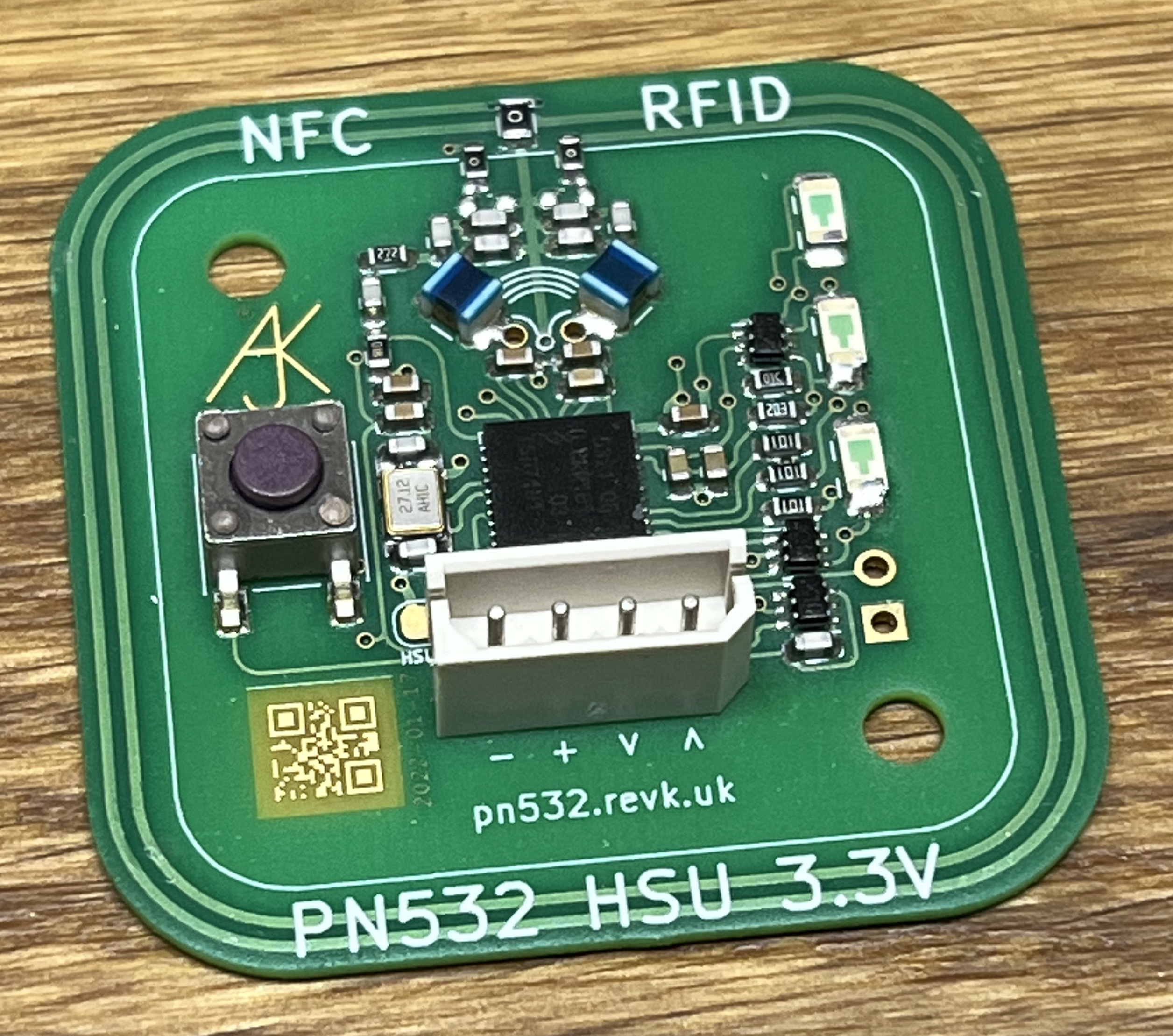
I have been working with ESP8266 controllers and NFC readers. My preferred reader is the PN532 based Elechouse reader. As I have noted before, buy from Elechouse direct as there are a lot of bad copies!

However, when connecting to the processor I have a choice of interface. It is one of the rather nice features of the PN532. There are three interface types I²C, SPI or HSU.

So how to choose...

I²C

I²C stands for Inter-Integrated Circuit, so the acronym is IIC, but someone thought it would be fun to treat letters in an acronym in the same way as algebraic variables and write II as I². Arrg!

It is a simple bus for connecting devices and uses a clock and data line. Wikipedia has details (here). Both clock and data lines have a passive pull-up resistor and are actively driven low by master or slave. The protocol is well defined, and works well. It allows multiple devices on one bus and is very popular for a lot of peripherals.

Looking at the Elechouse web site I saw this: "On-board level shifter, Standard 5V TTL for I2C and UART, 3.3V TTL SPI" which rather concerned me. The ESP8266 is all 3.3V, and I did not want to have to mess about. This immediately put me off using I²C. However, looking at the schematic, the level shifter is completely optional, in that the same two pins are used for SPI, I²C and HSU and connections have these at the 3.3V level direct from the PN532 (via 100Ω) as well as via the level shifter, so it can be used for HSU and I²C if you want.

✓ Only two wires, simplifies wiring and frees up GPIO pins
✘ ESP8266 does not have hardware I²C support, so uses more processor and is slower
✓ ESP8266 has software I²C which means almost any GPIO pins can be used for clock and data, making PCB layout much simpler.
✘ Data sheet suggested level shifted to 5V (which turns out to be optional)
✘ Both clock and data use passive pull up resistors, meaning they can be subject to more interference on long lines

SPI

SPI stands for Serial Peripheral Interface. Wikipedia has details (here). It is more complex than I²C in the way it works - using 4 wires not 2, and allowing different configurations. It is also quite fast, allowing several MHz operation.

The ESP8266 has hardware support for SPI, which is good, but the downside of that is that specific GPIO pins are used for 3 of the 4 signals, so PCB layout is more complex.

✘ Four wires, so more to connect from controller to reader and uses more GPIO pins
✓ ESP8266 has hardware support, so allows faster working
✘ ESP8266 has hardware support, so the pin assignments are fixed making PCB layout more complex
✓ Lines are driven (from master or from slave) rather than using passive pull ups
✓ 3.3V direct connection to ESP8266

HSU

HSU stands for High Speed UART. This is simple old fashioned serial communications, on a Tx and Rx line, and defaults to 115,200 Baud.

The ESP8266 has hardware support for UART, and will work at these speeds. The ESP8266 library has good, interrupt based, serial handling. Unlike SPI there is actually a choice of pins that can be used, but this is still a tad limited. Of course the ESP8266 uses the UART for other things like programming and debug, but there is an additional Tx available for debug (Serial1).

✓ Only two wires, simplifies wiring and frees up GPIO pins
✓ ESP8266 has good hardware and library support for serial UART
✘ Pin usage is a fixed, but a choice of two sets
✘ Data sheet suggested level shifted to 5V (which turns out to be optional)
✘ Serial on ESP8266 is used for programming and debug
✓ Tx and Rx are driven (one each way) rather than passive pull up resistors
✓ The same connector can use used for programming and connection to PN532, reducing number of headers needed on the board

What did I do?

I was initially put off by the level convertor comment, leaving SPI as the only option. The first project I made using an NFC reader was connected to weighing scales, and used the serial on the ESP8266 to talk to the scales, so that rules out HSU. So SPI it is.

There are 4 connections needed (so 6 wires including power and ground). This means you can use 5 pins in a row on the ESP8266 (VCC, D13, D12, D14, D16) and GND to make a 6 way connector. Sadly the pins are not quite the same order as on the Elechouse PN532 board. This just means the connectors need wiring carefully.

This works well. I then used the same design for the door controller.

Hindsight

Firstly, the fact that the level convertors are optional means I²C and HSU are an option. I could have, for example, used I²C on a smaller ESP-01 for the scales rather than using an ESP-12F and SPI. However, the use of passive pull-ups is still a concern if the reader is on any length of wire from the controller as may be the case on a door controller. I could have used HSU, as the ESP8266 libraries have a soft serial mode, which can work at the scales 9,600 Baud rate, so could have used Tx/Rx for PN532 and one of the other pins to talk to the scales serial interface, and used an ESP-01.

I have since tried HSU, which just works, and is only 4 wires to the reader (power, ground, Tx and Rx). I was concerned that it would be slower (115,200 Baud rather than 2MHz) but actually it is slightly quicker (28ms rather than 30ms for InListPassiveTarget on same card), and a lot of the time is the PN532 operation and the NFC card itself. The Baud rate can also be configured!

It also turns out that had I used the more usual GPIO15 as the SPI SS pin not GPIO16 I would have actually wired the PN532 such that it could be used for HSU or SPI, as the PN532 uses MOSI for Tx and SS for Rx and the ESP8266 alternative Tx/Rx for UART0 are on those pins!

In practice, what I have done is make a 4 pin header with GND, 3V3, Tx and Rx. This is the same order as the 4 pins on the Elechouse board, but is also a header that can be used for programming the ESP8266.

I am slightly kicking myself for not trying HSU and I²C to start with, but to be honest I was just pleased to get things working. Freeing up two extra GPIO pins is nice, as is having fewer wires to reader, and pins in the same order both ends of the cable. The libraries do, however, make it very easy to change interface. Just remember to set the switches on the Elechouse board to match what you are using.

2019-05-02

PN532 Disappointing electronics

Playing around with some electronics is fun, and usually things work well, but I have hit a slight snag.

I am trying to make a more secure door entry reader using NFC. The main idea is to work with Mifare DESFire EV1 cards using AES. This would be secure.

The first reader I tried was an MFR522. This works well on the Mifare Classic cards, and it is easy to make something that uses the card ID (4 bytes) as an access control. But they can be copied. Even using the encryption is pointless as Mifare Classic cards have been well cracked.

Apparently the RC522 cannot handle the better cards, so I got a PN532 based reader. One of these red ones...


They are readily available on Amazon (with a header, card, and fob).

I got one, tried it, it worked. It would read a card or a fob, and would read the 7 byte ID from the better Mifare DESFire EV1 tags. This is excellent. It even got an ID (randomised) from my passport!

I then 3D printed a nice case for it, and reconnected it, backwards! I have since changed to properly polarised connectors, but I was cursing. It stopped working, unsurprisingly.

So I got another one. It reads the Mifare classic cards, but has to be very close to the reader. It won't read the Mifare classic fob that came with it even. It won't read my passport not the Mifare DESFire EV1 card.

So I got another one, and the same. Arrrg!

So I got another make, a keyestudio one. It won't read the Mifare DESfire EV1.

This is really frustrating. Looking around the internet it seems some of the red boards work and some don't. There are reports of changing some components on them. There is talk of cheap Chinese clones which don't work well. The elechouse website even has details of the cheap copies being sold.

However, it seems I can buy genuine parts from elechouse, so I'll try that. Fingers crossed.

P.S.... 

Hi,
It is Holiday of Labor's Day here.
We will ship your order next week. The shipping would take 5~7 days.

QR abuse...

I'm known for QR code stuff, and my library, but I have done some abuse of them for fun - I did round pixels  rather than rectangular, f...