A company called Elechouse make a PN532 RFID reader board.
There are actually a few PN532 boards available, but the Elechouse one seems to be the most popular. Annoyingly, it seems that there are a lot of cheap copies that don't work as well. It has a number of advantages over the alternatives, mainly (I think) its compact design.
The actual circuit is basically the PN532 reference design from the datasheet.
However, there are a few niggles I have with it where I have used it in projects. My main use case was where this is the external module on an access control system, in a small case. The main issue was it lacked any feedback (e.g. LEDs). I worked around this by using its internal GPIO pins to work a red/green LED, and a tamper switch.
So I was thinking, I could make my own board. The issue for a home made board is soldering the PN532 itself, but I have been practising and am reasonably confident that with a hot air gun I can manage it. The result would be an open source PCB that can be home made. Obviously it could be properly made with pick and place and sold as well.
I am concerned over "feature creep" in such a design, and even just pondering it for a few minutes I am already seeing ways I could be improved on. Thankfully a lot of features could be "optional fit" on the PCB, basically adding no cost when not needed.
But I am in two minds over making this - it will not take too long to design and have made, but may need some tinkering to ensure I have the antenna matching right (and I may even need help with that). Before I start, I am interested in feedback, especially from anyone that may think they would like to use it themselves.
So here are my design thoughts.
- A small square board (note the Elechouse is not actually square, but I am thinking the same sort of size, maybe 42mm x 42mm) with simple mounting holes.
- Components can be only on one side making easier to mount (same as Elechouse).
- Using larger (e.g. 1206) components that can more easily be hand soldered.
- Not having the big DIP switch - I am thinking fixed HSU mode, but maybe pads for a link to make I2C mode as they use the same pins. This is to keep the profile low, and hence easier to fit in a smaller case. My testing suggested HSU is just as fast as I2C for actual card access, and much more reliable as tx/rx are driven at each end not just pulled up like I2C, so survive a long cable. So HSU is likely to be the fixed mode for this board.
- Whilst it may have additional pads, the main 4 pins for connection are GND, VBAT, TX, RX (Note TX/RX could be I2C). The VBAT can be 3.3V to 5V but signals would be 3.3V.
- The 4 pins for connection would probably be 0.1" header, and 2.5mm SPOX (straight or right angle) header, and 2x2 molex milli-grid in the centre of the board. Design to allow connectors to be either side of the board. This makes mounting as a reader very flexible.
- Pad to allow a contact switch on either side of the board as a tamper contact - connected to a GPIO pin.
- Three LEDs arranged in a corner in traffic light style, Red / Amber / Green, connected to GPIO pins. This is perhaps the most important feature as it allows feedback to a user. These can be pads for a small 1206 LED as well as through plated for standard leaded LEDs. Again, making pads both sides to allow LEDs to be either side as needed. Leaded LEDs can be more useful in a simple case design instead of light pipes.
Some possible feature creep...
- An FTDI FT230X and 4 pins for USB lead connection, so can be used as serial to HSU mode USB device. This would allow it to work as a USB connected reader and hence for applications using a Raspberry Pi, or simply for connection to a PC for configuring cards on a security system. Given that you can so easily get an FTDI in a USB plug and serial lead, this probably really is unnecessary as that could be used with the 4 pin serial connection directly with ease.
Obviously I can include some 3D case designs too.
But I am interested in feedback - would you use such a board? Would you make one yourself if I do this (all open source)? Would you need other features? Would you take away any features I have suggested?
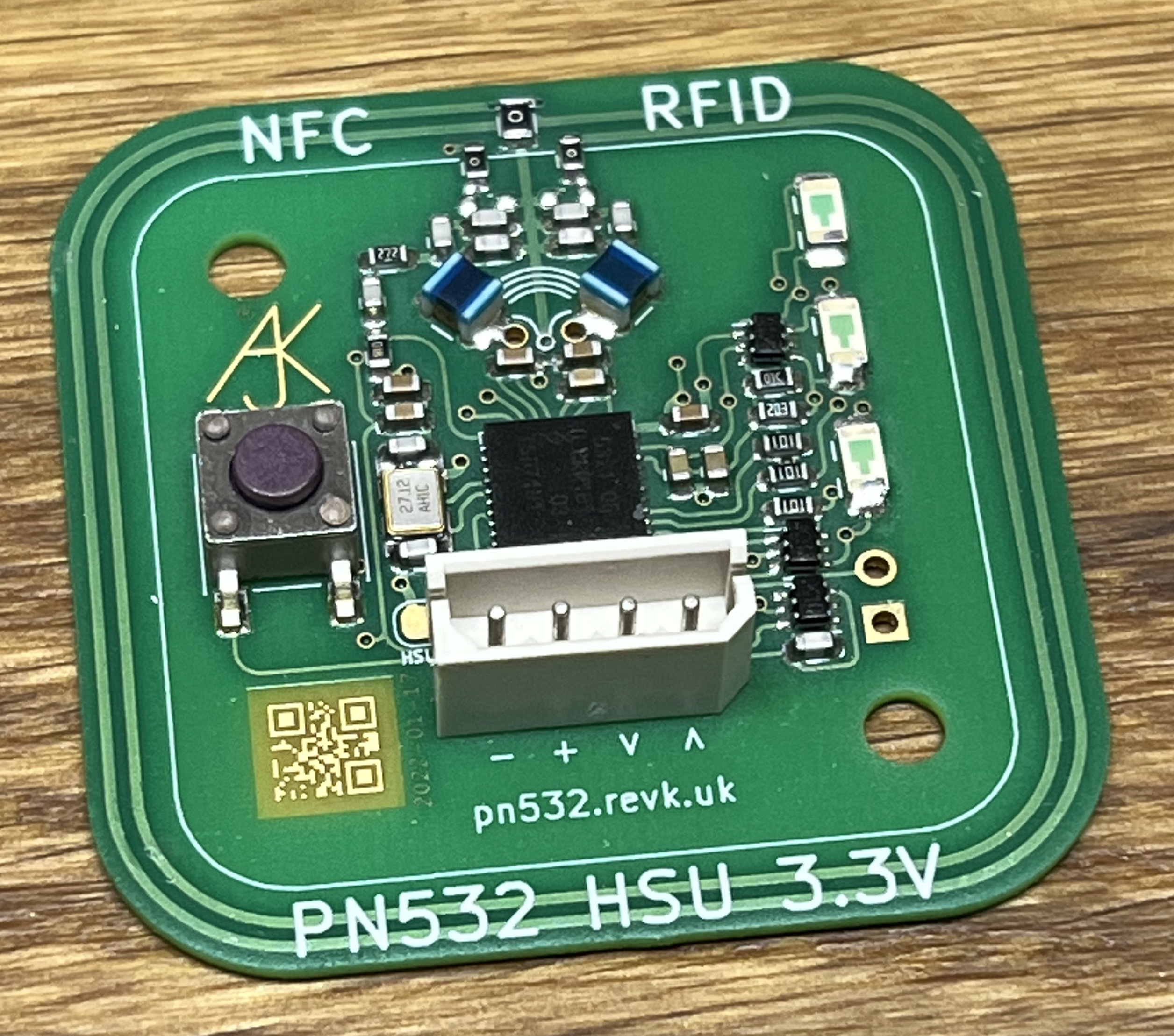
P.S. This is the sort of idea... Though obviously this shows multiple connectors when you would only use one. This idea is any of the connectors, switch, and LEDs could go either side as required. OK I have ordered these...

P.P.S. Err, it works. OK one of the LEDs does not, as on P34, which I just cannot get to be GPIO for some reason, and the crystal pin out was wrong, but it actually talks NFC!!!! I am gob smacked. More in a later blog.