Showing posts with label ESP32-WROOM-32. Show all posts

2022-02-28

ESP32-PICO-MINI-02

I started playing with Espressif processors with the ESP8266, and quickly moved to the ESP32. The main module I have been using is the ESP32-WROOM-32. Using a module avoid having to mess with RF directly, and makes it a lot easier.

However, I have now discovered the new ESP32-PICO-MINI-02 module.

It is quite impressive.

  1. It is smaller, half the size of the ESP32-WROOM-32.
  2. It has more flash (8MB not 4MB, though WROOM modules can have more).
  3. It has SPI RAM (2MB) so a total of 2½MB RAM rather than just ½MB. Impressive.
  4. It cannot be hand soldered as pads underneath the module.
  5. Did I say it was tiny?

How is it so small? Well, unlike the ESP32-WROOM-32, which is several devices in the module (the processor and a flash), it is all one chip. They have integrated the flash and SPI RAM all in one device.

So, armed with this impressive new chip, I have been playing around with my various designs. Re-designing a board to use this is simple at the schematic level, but more of a challenge when it comes to layout. The good news is I am better at layout now, and doing a board a second time is easier, so I have managed to make all my various designs much smaller. This is quite helpful for things like the alarm system controller which has to fit in an EXIT button back box, and can be a squeeze, or even the Galaxy keypad controller than fits in a small gap in the case.

I have taken the chance to tidy up my designs a bit as well, lower power when not using USB, by turning off the USB controller, etc.

I have also designed to make some more boards - including a small generic module, using this:-

This provides 10 GPIO pins, but is a tiny board. I've also made a GPS board.

I was obviously a bit worried about a new module - did I read the data sheet right? Can I solder it (using solder paste) properly? Well I am pleased to say, it worked first time. Yay!

Update: The GPS module works as well. It is fun as has a few GPIOs not normally on the WROOM module (7, 8, and 20). It is worth noting that it uses an ESP32-PICO-V3-02 chip, the V3 and 02 all make slight differences, so worth checking data sheets carefully.

2022-02-10

And another board

And another board, just works.

One of the designs I made a while ago was a very small "generic" ESP32-WROOM-32 module. It had a 6 pin connector (normally a SPOX 2.5mm, but can be 0.1" headers). It was GND and 5 GPIO pins. It really was tiny, and has proved very useful.

But occasionally I need more pins, and a full size general dev board is much more bulky.

So I made a Mk2 that is a bit bigger. 2x8 pins, all of which can be GPIO. By default one each side is GND, and the next ones can be linked to DC supply or 3.3V. 6 of the 8 have BAV99 diodes for ESD protection as well. The whole thing can be powered from DC contacts (4V-40V) or a USB-C lead. The USB does serial to make easy to load code, and there is an RGB LED as well.

It is still pretty small, but a bit more useful.

2022-01-30

More on KICad 6 and PCBs

I have been updating all my PCB designs to allow for using the more commonly available LMR16006 with variable voltage, rather than the fixed 3.3V regulator. All done now.

But I have also made a couple more boards.

For a start, an ESP32-WROOM-32 board with more GPIOs. The previous generic board was this.

It has 6 pins, GND plus 5xGPIO with some links. I have updated the silkscreen to have GPIO numbers all over the place as it is a pain to find them on older boards if not printed on the board!

But I decided a more powerful generic design may be in order, so did this new one today...

This is a tad bigger, but 16 GPIO pins. Yes, one each side is pre-linked to GND, but can be cut. And options to link to DC supply or 3.3V are always useful. Again, an RGB LED on board. And I have labelled all the GPIO numbers. This should be useful.

But this has been a busy weekend, and I have also made this...

Now this is a fun board, an interface for an ASR33 using 20mA current loop. It uses some simple ICs that are aimed at providing fixed current driver for LEDs, but seem ideal for this use. For avoidance of doubt this is not the same as 4-20mA current loop used for some control systems (an analogue signal level), but a simple make/break on 20mA, and used for teletypes 50+ years ago.

All of these will be a little over a week to arrive, so fun to test when they get here. I'll post more, specifically on the ASR33 board, once I have them.

To be honest I am amazed how easy KiCad makes it to just knock out a circuit design, do PCB layout, and be all ready to order actual boards.

2021-05-28

Battery powered

My latest project is to make something battery powered, based on an ESP32 processor. The ESP32 data sheet claims it can go down to under 1uA in a deep sleep mode. It also has an Ultra Low Power processor that can do things in deep sleep at only a few uA. It is not very clear in the datasheet for the ESP32-WROOM-32 module how low it can go - after all that has extra bits including an external flash. So it was a bit of an unknown. However, I have made something, and it works... (on GitHub)

The first board was a cock up - wrong footprint completely on a key device - kicking myself. The second version was more what I would expect - some minor errors I could work around, allowing me to prove it all works and confirm power usage. The 3rd version was great except one of the chips again had wrong footprint - but this time close enough for the device to fit without problem. I have managed to keep the device tiny - not much bigger than the ESP32-WROOM-32 itself.

The first application is actually to work with a VL53L0X ranger in the top of an oil tank, running on battery and reporting over WiFi. The next trick may be LoRa for such things.

Battery / power supply?

The first real question was whether to try and run directly from a battery, or to use a power supply?

Directly from a battery means finding a battery that is within spec to produce 3.3V. The voltage from a battery is often slightly more (when new) than stated, and depends on the battery technology. The processor will cope with voltages a bit out of range as well (3.0V to 3.6V). So a 3V battery should work. But the voltage drops as the battery runs down, and we are starting on the edge of acceptable voltages, so this could cause problems. The advantage of running directly from a battery, apart from fewer components, is the really low power modes of the ESP32 should allow a really long battery life.

With a power supply you have the advantage of using a wide range of battery, e.g. 4.5V, 9V, 12V, etc, but the big disadvantage of wasting power on the regulator itself.

I ended up using the LMR16006 from TI which is designed for battery devices, and has an idle current of 28uA when not driving much load (e.g. an ESP32 in deep sleep). It also has a shutdown mode drawing less than 1uA (see more on that later).

However, testing showed that it draws 34uA when not even connected to a load. This pretty much is explained by the 460kΩ potential divide built in to the fixed 3.3V module to drive its feedback pin. I could go for external potential divide but 460kΩ is on the top range recommended in the data sheet.

However, even 34uA is good, and can allow a battery to last years.

USB as well?

Do I need USB as well? Well, no, not really, I could have a generic programming header, but I like the USB-C connectors. They are good as a power supply when not running off battery, and make programming and debug easy. So yes, I'd like to keep the USB.

The issue is power. The USB chip (FT231X) can be powered from USB, and even work its own 3.3V I/O from that. So it can be totally off when no USB. Good.

But it is used to control EN/GPIO0 to reset and put the ESP32 in boot mode. If USB is off, the ESP32 stays in reset. Thankfully the USB chip can be configured to invert RTS and DTR if you want, so I put them through a simple transistor inverter so that when the USB is off the ESP32 is not in reset or boot mode. The result then works as expected with the debug and flashing tools in the ESP IDF.

The Tx pin to the USB when powered down was a concern, but it seems to cause no problem, and the code can turn it off immediately on start up, and in deep sleep it is not connected.

The USB chip can also feed in some useful GPIO pins, reporting when it is on (a fixed "1" on a CBUS pin), and even if it is connected to a charger not a USB device. This means the software can tell if running from battery or not, and stay awake when being used for USB debug.

How low does the ESP32-WROOM-32 go?

Well, the good news is that the ESP32-WROOM-32 does indeed use bugger all (aka 1uA) in deep sleep. This is impressive, so we are looking at under 35uA idle current for the whole board from a 9V supply when idle.

Obviously we need to wake up occasionally, but we can wake up, boot, connect to WiFi, connect to MQTT, report status, and shut down in under a second with fixed IP. Indeed, the WiFi can be in use for under half a second, which is impressive. We need to do some long term tests to confirm battery life.

Measuring the voltage?

Of course, one thing we want to measure is the battery voltage. That allows us to see if we have a low battery. It is essential for any battery based device to tell you the battery is low. The answer is a simple potential divide feeding an ADC input to the ESP32. Except that draws current! Even 1MΩ divide is 9uA at 9V, 100% of the time.

The answer is a FET, well, two FETs. I am not an electrical engineer so this needed a bit of research. One FET or transistor would not work as it had to be at the "top" of the divider. If it was at the bottom of the divider it would mean 9V going in to the ADC pin when the FET was off. But when at the top of the divider you don't have GND as a reference to drive the FET.

The answer is an N-channel FET driving a P-channel FET, all in one package. Thanks to twitter for help on this. It works! I can turn on the divider, take a reading, and turn off again. I have some resistors to ensure than when GPIOs are isolated the FET stays off anyway. Sorted.

How low can you go?

Can I do better than 35uA? Well, yes, probably. The ESP32-WROOM-32 itself goes down to 1uA or so. The regulator in shutdown goes to 1uA but as that annoying potential divider still. If I was able to shutdown and disconnect the power from the ESP32-WROOM-32, it could run off a capacitor for many seconds at 1uA.

So basically I'd need a way for the processor to turn off its own power most of the time!

The trick is ensuring that if you sleep too long, the power will come back on anyway, and indeed when first powered up.

I think I can do this with another FET, pulling the shutdown pin to GND, driven from a GPIO pin. When no power the GPIO will go to ground, pulled by parasitic diodes if nothing else, and cause the FET to go off. Of course you still have the issue of making the shutdown pin then go high when the FET is off, with the only power being the battery, so you still need that one pull up resistor. I wonder how big we can make it? If we can make it 10MΩ we waste only 1uA on that.

The same signal driving the shutdown pin could also drive a FET switching the feedback potential divider, so we turn that off too. It may need some careful design, e.g. FET at bottom of that divide, to ensure we don't fool the regulator in to supplying too much power because its feedback is not get connected, but that should not be rocket science.

For now, I'll test using the current design, idling at 35uA, and see how it goes. But I may yet make a new version that tries to turn itself off most of the time :-)

P.S. I am such a fan of solder paste now, I can't see me ordering boards without getting a stencil as well. It is so quick and so reliable, it is quite amazing really...

2021-03-11

Hobby PCBs

Milling PCBs

As some of you may know, from previous blog posts, I got quite good at milling PCBs. Basically, if you want to make small circuits at home, one option is a milling machine.

It does have some key advantages - the main one being time. You can have an idea in the morning, and design a circuit, layout a PCB, mill it, and have it soldered and working by lunch time. You can do several iterations of a board during a day. Another advantage is the cost - just the cost of the copper clad board, and the occasional new drill bit.

However, there are limitations. The main issue is that is it single sided - whilst a double sided milled board can just about be done, it is hard to align and the holes are not plated, so need links. The accuracy is an issue too - using a USB-C connector was just at the limit of possible, mainly as I only needed to connect two of the smaller pins (CC1/CC2), and even then - the more detail you try and do, the harder it is to get right first time.

So, moving on - what else is there? What I am doing is not quite hobby, it is more R&D, so I need slightly better than just milled board. The answer is getting fast turnaround PCBs professionally made. The nice thing is that double sided and plated through hole now becomes the norm.

KiCad

But before I could get boards made, I needed a new way to design them. For milling boards I was using inkscape to lay out the milling path. That was not going to cut it when someone wants Gerber files. So I asked Twitter, and several people suggested KiCad - a free package that was available to run on my Mac.

It is nice, I have to say. It does the schematic, and then one button and you are in to PCB layout. It has design rule checks at each stage. The PCB layout is nice - I worked out that I prefer the "push" mode where running a new track which pushes the existing ones out of the way. It has limitations, but makes it easy. The other trick I did not realise initially is I can redraw an existing track in a new direction and it will remove the original part I have now bypassed, allowing more major track moves than "push" can handle, and making it easy to do cosmetic tidy up at the end.

It also does a lovely 3D view, and it seems that not only does its built in library have 3D models for lots of things, most components have them available as standard now. Even complex modules like the Pololu D24V5F3 regulator has one. I was able to add new parts at schematic, footprint, and 3D model without any real problems.

And, of course, it will simply make Gerber files and Excelon drill files, at the click of a button.

It is also rather nice being able to design for double sided with fine tracks - it makes it way easier to track boards and allows me to make a much smaller board.

PCBTrain

So, I sent the Gerbers to PCBTrain. And two days later, they arrive. they look good.


They look nice. They are their quick turnaround product, which is copper with silver, and no solder resist or silk screen, but they work.

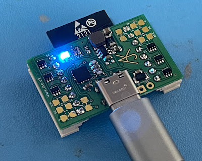
I even got good at soldering things like the USB-C connector.


The trick was lots of flux, and a good soldering iron. Tinning the pads first and then just heating the pin to fix it. It takes a bit of practice :-)

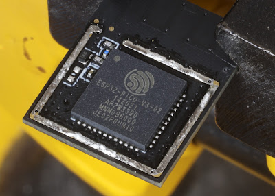
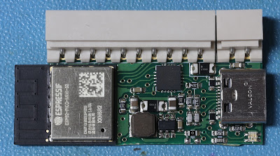
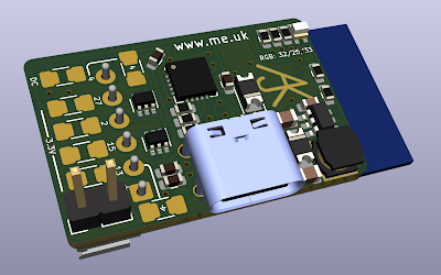
Tiny ESP32-WROOM-32 board

My first project to test the whole process was a minimal usable ESP32-WROOM-32 board. The idea was a board with USB-C or DC power, several GPIO on a connector, and built in serial for programming. The challenge was to make a small as possible. I think it came out well.

The result is tiny. But with 5 GPIO pins it is very flexible for all sorts of IoT applications. There is no way I could have made this on a single sided or milled board.

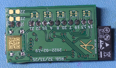
I also made each GPIO have pads for a pull up resistor, or, if powering something from the connector, a zero ohm link. This works well for things like a DS18B20, but could be connected to all sorts of things like an RFID reader, a GPS module, or whatever. It has enough pins that this module could run my ASR33 teletype, and be a lot smaller and neater than the node-mcu board I am using now (so that may happen).

One nasty hack was the USB connector I am using is through hole - as that makes it a lot more robust (their is nothing more annoying with these than pulling the connector off the pads by mistake). To do this I ended up with holes going through 4 of the GPIO pads on the ESP32 module. But it has a lot of GPIO, and they default to input, so no problem, as long as the software knows not to use them. Obviously I had to tell the schematic that they were grounded too.

Another trick was the the Pololu module was not fitted using pins. I could use pins and clip them short, but as it happens, with the through plated holes, just solder down the holes secures it nicely. I only use 3 of the 4 pins, as that would have put a pin through the ESP module pads too, and not in a good way this time. I did have to remember to put a pad under the 4th pin else it ended up on a GND fill which would have been bad.

The end result really is quite small.

FTDI FT230X USB/Serial

The final new bit for me was building in serial for programming. Previously I had made designs using a 4 pin SPOX connector which connected to a serial/USB lead. This takes quite a bit of board space. So I investigated serial USB chips. FTDI seem to be the king of serial USB, and they do a small 16 pin QFN-16 package module, the FT320X. I checked some videos of people soldering QFN packages by hand, and figured I'd be able to.

It is a nice small chip, connects to USB, and provides serial with Tx, Rx, RTS, and CTS as well as 4 configurable CBUS pins. It even has a 3.3V regulator, though sadly not enough to run the ESP32 - that would have been awesome!

There is one small downside - it needs a few passives. That is a pain on a small hand soldered board, and where I am trying to make it tiny (just for fun), so I built without the passives. This will mean the USB is not properly impedance matched. But it is good enough for programming in my tests, and that is all the serial lead is actually for. So what the hell? OK, yes, it annoys me to cut corners even on a fun board and I may try to at least squeeze the 27R series resistors at some point. I am not normally one to cut corners.

However, the small size, and passives, were not the only issue. I decided to connect RTS to the EN (reset) pin on the ESP32. This is a common trick and the tools, like the ESP IDF flash tool, pull RTS low and then high to reset. It is risky in a way as a "normal" serial port will make RTS low when ready for the ESP to send data, but it seems the common tools do not, so it works. What I was unsure of until I tested is that this pin stays high when otherwise idle, and when connected just to power and not a USB driver, and so on. It does. It works. Yay!

However, to program an ESP you need to put in to boot mode, and this means pulling GPIO0 low during reset. Most boards have a button for this which you have to hold when programming. Apparently some do a trick with DTR, including the ESP IDF flashing tools.

Snag! There is no DTR on the FT230X. What is extra weird is that DTR is not one of the CBUS pin modes, so you can't even create a DTR. This seems an oversight as other FTDi chips have DTR, DSR, DCD, and RI, so why are they not options on CBUS pins? Why does this matter? - well a normal serial driver will be able to control RTS and DTR as they are standard pins. To control special pins like CBUS on the FTDI needs code written specifically for the FTDI, not just any serial connection. So not using DTR makes it "special".

I considered just adding a button, but a bit more research has led me to use CBUS0. The problem then is how do you use CBUS0? It has multiple functions (not DTR, sadly), which can be configured.

FTDI EEPOM

The answer is that you programme the EEPROM in the FTDI chip. This lets you set a manufacturer, description, serial number, PID/VID, and a load of settings. One such setting is what each CBUS pin does. One of the options is a GPIO. So that is all I have to do - zap the EEPROM with the right data.

Snag! There is a tool, ftdi_eeprom, that is simple to install on a Mac. But it only lets you set a few things from a config file, and not CBUS functions. And even though it will read the EEPROM to file, it won't just write a file to the EEPROM - it insists on "building" it from your config, even bits you might have deliberately set in the file, like CBUS functions. Arrrg!

So I ended up making a tools, ftdizap, which allows me to simpley set certain (well, any) settings in the EEPROM. I also made it work the CBUS pins when set to GPIPO mode so it can control the output on the CBUS pins directly as a command line tool.

This means I can flash by using ftdizap to set CBUS0 low, then running make flash, then setting CBUS0 high and resetting with RTS low/high. It works on my Mac and on my linux machine. So, simples. A minor tweak to the make file, and I can simple make and flash new code in one go - no button pressing. The make monitor also works, leaving RTS high, allowing debug.

I also set the other CBUS pins to various modes and connected to GPIO on the ESP32. This allows the code to tell if in a "charger" mode, or if simply "not connected to a USB host", or if "put in to USB sleep mode". All of which could be useful in some circumstances.

What next

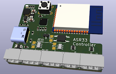
I already have another board design - this one slightly more useful. It is a small board the same size as a 1.5" RGB OLED display modules (commonly on Amazon). It fits all the necessary components between the board and the display, including a USB-C socket, and the FT230X. It has an 8 way SPOX socket so providing 7 GPIO pins. It has pads for DC power alternative to USB power. It also has pads to allow an SCD30 CO₂ module to be fitted to the back to make a complete environmental monitor. The pull up resistors on the GPIO allow it to be set up for a DS18B20, and the choice of SPOX sockets allows for a 3 pin SPOX plug connected to a DS18B20 to go in to the 8 pin SPOX socket nicely. It should make for a very flexible board.

As you can see KiCad does a nice rendering of what it will look like.

Published?

Yes, the code, and the boards, are all on my GitHub. Just bear in mind that they are likely to have several updates over the next few days.

2019-10-27

ESP-IDF re-partitioning the flash on the fly

The ESP32-WROOM-32 has a 4M flash, which is usually carved up for boot loader, some small areas (NVS, etc), and then three code image spaces: 1 for "factory", and two "OTA" areas which alternate. Well, that is one of the two defaults you can set.

Sadly, even the most basic of code, with even log levels of logging enabled can easily hit a 1M code space limit. So I decided to make a new partition table.

Just two OTA spaces

The first thing I confirmed is that if I just have two OTA areas, and no "factory" area, it works fine. It can alternate the OTA flashing, and make flash just flashes the first OTA area.

Oddly, it looks to me like you can have two OTA areas of 0x1F8000 but the make system said it would not fit. I ended up going for 0x1F0000 which is close to 2M.

On the fly update

The real trick was changing the partition table on the fly. The key issue here was ensuring the original factory build was in the same place as the first new OTA block. I changed from factory+ota_0+ota_1 to just ota_0+ota_1 at 0x10000. This meant, whichever image I was running, by changing the partition table a reboot would find the factory release (in ota_0) and run it.

I simply had to erase and re-flash the partition block. I obtained the signed binary partition from the build directory and embedded. Then I just reboot, and sorted. Obviously you then need an OTA upgrade to move off the original factory code.

The simplest check was to compare the current partition table with the one I want, and if different, re-flash and reboot.

You do need to tell the SPI flash component to allow you to erase/write to dangerous areas of flash, but otherwise the code was pretty simple.

End result, I have nearly twice the code space.

2019-08-21

ESP32 progress

I am, of course, reinventing wheels, yet again with my move to ESP32 for IoT and access control stuff.

It is going well - I am actually on holiday in Greece, but whilst my wife and daughter sit on sun beds, I have been messing with code. Yes, I took a laptop, programming cable, some ESP32 boards, and even a hand held oscilloscope on holiday with me. Sorry. I spent 4 hours on the plane reading the data sheet on my iPad!

My plan is to get my ESP32 development environment and toolkit working like I had on the ESP8266, and build up my "Solar System" alarm and door control module code.

In some ways this is a nice project - it is often good to rework and redesign something for the second time as you have learned lessons and can do things better. It is also nice that my code effectively has a specification to work to. The previous code was being specified, designed, and coded all at once. But now I have a system which works with the ESP8266 modules and should work just the same with the ESP32 modules.

Progress

I am making good progress. I have the build environment on Mac and linux working. The instructions were very clear. I am actually ssh'd to my linux box to develop now. I have the basic support system which allows me to connect to the WiFi, and MQTT server, and do over the air s/w updates, and store settings in non volatile storage. These are all based on the ESP-IDF tools, which seem quite good.

I have hit a few snags - for example I cannot do certificate pinning on the TLS using the SHA1 hash of the certificate, it seems. I have to include the PEM format certificate itself. This seems needlessly complicated, but not a big change.

I have a snag with MQTT that it seems not to pass on messages with zero length data for some reason. I may have to work that out and do a pull request to the library.

I also have to restructure the design in some case - for example, previously I did the settings in a block of memory that was flashed. Now I am using the provided NVS library for settings. It seems good as it does not have to re-flash a block on every change - it incrementally updates a log of settings in flash as it goes. Quite sensible really. However, it seems to lack a means to enumerate the settings that are there - I have to ask for a setting by name. As a result I have changed my code structure to register settings from the application with my library. This has meant a redesign, but as always it makes it much better in the long run.

Update: As redesigns go - I ended up re-doing it yet again, and pretty slick now.

I should be able to sort the basic GPIO (inputs and outputs) really easily, and hence use almost all of my existing door control code with that. It looks like I can compile my linux version of DESFire stuff for NFC too, so no need for an ESP specific version (if needs ESP specific AES calls).

There will be some challenges with the PN532 library and VL53L0X library I expect. But they are not rocket science, thankfully. The Honeywell Galaxy RS485 bus should just work if I can work out the timer interrupt logic. Saldy each of these is simple in theory but getting my head around the specific way of working for the ESP32 takes an unknown amount of time. Interrupts were a challenge on the ESP8266!

PCB design

This had me kicking myself the night before we left on holiday. I have made up several ESP32 based PCBs. A general break out board; a door controller board; and several Galaxy keypad boards. I had checked I could load code on the door controller. It worked.

But I realised, on reading more of the data sheet, that 6 of the pins on the bottom of the module (ESP32-WROOM-32) are connected to the internal flash and so unusable. Why even have them come out of the module then? They are literally in the way of tracking the usable pins out of the chip. I had the same issue on the ESP-12F and taped over the pads. The ESP-12S sensibly does not have them, but then has a GND pad you have to tape over if you have tracks under it. The ESP32-WROOM-32 has both unusable pins on the end and a GND pad in the way. Arrrg! Even worse, it is only 6 pins of 10 at the end that you cannot use, so not actually easy to tape over just the 6 and still sensibly solder to others. I had read a web site on "safe" GPIO pins, but that documented the ESP32 chip not the ESP32-WROOM-32 module, and for that the pins 6-11 are "safe" to use as GPIO. There are other pins that are iffy - i.e. needs to be high or low at boot. Those I knew about.

The end result is that the keypad boards I made would simply not work! So I was left with three boards in total to take on holiday. The door controller would not "work" for the GPIO pins, but they are not connected to anything that would stop the chip actually working. So usable for developing code. I have managed to trash one board already with a flash / secure boot mix up!

The first thing I did when I got here was re-work my designs on the basis of taping all 10 connectors on the end of the chip. If I had not, it would have been bugging me all holiday. I had to be a bit creative in some cases, but I managed to redesign both boards. I'll mill them when I get back (I don't think my wife would have let me bring the milling machine on holiday for some reason).

Door controller PCB

Update: The RS485 is a challenge. I made a low level bit bashed solution for ESP8266, which I could use. It uses two pins, a Tx/Rx and a DE/RE pin. But the UARTs in the ESP32 have hardware support for RS485 as do the drivers, and are better done with separate Tx, Rx, and DE (RE permanently enabled). So I may re-track the PCB and make a driver using the UART. Again, a redesign of both PCB and code. Overall this is dragging on longer than expected.

Security

Security with any IoT stuff is important, and reading the data sheets on the ESP32 and using the build environment, I can see that Espressif have done their homework. Nothing is 100% secure, but they are really trying hard here - which is good news as a lot of IoT stuff is totally crap!

The chip has a secure boot mode. This means the first stage bootloader in ROM checks the signature on the bootloader in flash before running it. The second stage bootloader checks the signature on the application. Doing an OTA (over the air) s/w update also checks the signature, even. This means you cannot load wrong code on the chip!

It also supports encrypted flash. This means that I can have the code, and all my settings (like login details to the MQTT server, and WiFi) securely stored in the flash. Even pulling it off the board won't get you the data.

It has a set of eFuses, which are built in to the chip. They can only be "blown", so are bits you cannot unset once set. These include bits that stop you reading the eFuses, but they are wired internally in the chip hardware allowing it to encrypt and decrypt the flash. You can even set a fuse to disable the JTAG debug port. This means you can really lock it down so that you cannot get credentials out of the chip or the flash. It might not stop someone de-capping the chip package and using a microscope to read the fuses, but it will stop most conceivable attacks.

They have built in AES, SHA, BIGNUM (RSA) and TRNG hardware as well, and the API makes using https and TLS simple and encouraged.

In short, security seems to have been done very well, and thought about at the outset in the hardware and software design. This is almost unheard of in the IoT world, which is generally pretty shit at security. Well done Espressif.

Update: I said nothing is 100% and a recent tweet suggests hackers have managed to crack it using clock or power glitching, but Espressif have replied saying they are adding hardware changes in the next release out soon! So they do seem to be trying, which is way better than most IoT stuff.

Opportunities

Once I have this starting point - code and PCBs - and it is working, then (apart from updating my existing door controllers), I have to think of other uses for these chips. They are packed with stuff - included a dedicated separate ultra low power processor. The opportunities for very low power devices are interesting. Even just the bluetooth looks fun - I could make it that door entry using a key fob needs to be able to see my phone in range, for example. I am sure there are a lot of opportunities!

They have some interesting direct AP-less WiFi modes in the API as well, and some low rate long range (e.g. 1km) WiFi functions too. There is even a MESH WiFi system. This all makes for some very interesting possibilities to make systems that do not rely on infrastructure such as access points.

I still have not made my environmental monitoring device yet, so that may well be the next project after this.

2019-08-15

ESP-01, ESP-12F, ESP-12S, ESP32

As I mentioned, I am trying to move my IoT development stuff to ESP32, and notably move from Arduino IDE to the native Espressif ESP32-IDF using mostly C.

This poses a slight problem. The development environments are sufficiently different that it is something of a pain in the arse to maintain both. Probably just about possible, but not simple. So I'd like to basically abandon the ESP8266 / Arduino stuff (I'll leave on GitHub) and start working only on the ESP32 based stuff.

This poses a slight snag as one of the use cases for this IoT stuff is a very small device placed inside a Honywell Galaxy alarm system keypad.

This is based on an ESP-01 module which is ESP8266 based. It is not ideal as not CE marked, no RF can, very limited IO pins, but it is small. It comes with a 2x4 0.1" pitch header and is just the right size to fit a Pololu 3V3 regulator between it and the PCB, which is rather neat.

This use case has the ESP-01, a 3V3 regulator, an RS485 SO8 driver, and a small 2x2 milli-grid header for programming and debugging.

The whole thing fits in the small space inside the keypad, as per the picture on the right.

As a result I assumed I'd be stuck with, at the very least, my keypad code on the ESP8266 / Arduino based code.

The other IoT devices are generally based on either ESP-12F, or preferably ESP-12S modules. These are only slightly narrower than the ESP32-WROOM-32 modules I am now using, and so easy enough to make alternative designs using the ESP32.

The ESP32, however, whilst larger, has a lot of IO pins. It is possible to track these pins so that you have quite a few usable IO pins, and GND and 3V3, all on one end of the chip if you try :-


I have actually tracked Tx/Rx programming pins, and GND and 3V3 "through" some unused GPIO pins, which allows its all to come out of the bottom end and keep the whole thing quite narrow. Obviously this is fine as long as I don't make those pins an output :-)

Once again, the new milling machine is doing a great job, and I was able to solder it.


And, to my delight, it fits, and the keyboard PCB fits over it with no problems!


So, yes, I can actually move away from ESP8266 now. I have to migrate and re-work the various tools and modules I have made, but once done, I can continue development on ESP32 only. Yay!

P.S. Always tweaking :-)


QR abuse...

I'm known for QR code stuff, and my library, but I have done some abuse of them for fun - I did round pixels  rather than rectangular, f...