Showing posts with label TASMOTA. Show all posts

2023-10-06

Shelly Plus 1 Mini

The new Shelly Plus 1 Mini is now available, and it is indeed tiny.

Note: Detailed instructions of upgrade from Shelly to Tasmota via web interface at the end of this blog.

Key differences from the Shelly Plus 1

  • Smaller (33½mm x 28mm x 16mm)
  • Cheaper
  • No DC power
  • No programming connections
  • 8A not 16A relay

The lack of programming header was a concern as I have always reflashed these using the programming header - but it can be done via the web control pages.

I did try, and failed, to find an image of the back of a Shelly Plus 1 Mini - so here you are...

It does still have a dry contact relay, making it suitable for working DC contacts (garage door opener, etc).

It still has the button on the back.

It still has an LED in the back.

It does still have the ESP32 processor.

But overall, this is a welcome addition to the Shelly family.

Inside

The inside is indeed compact. As you can see, the back does have programming pads. I have not worked out what they are yet, but should not be hard.


Upgrade to Tasmota

These are basically the steps from https://github.com/tasmota/mgos32-to-tasmota32 but with some explanation of exactly which menus to pick at each stage.

  1. You need to connect to the AP for the Shelly, and it does not pop up so you need to visit 192.168.33.1 to talk to its web interface.
  2. Select "Configure Wi-Fi Settings", tick "Enable Wi-Fi network", select SSID and enter password, and "Save settings". You then have to work out what IP address it is on as it does not say - you may have to check your DHCP server.
  3. You will need the right zip file. This lists them release section but on a mac you end up with an unzipped directory - you want the raw zip. Curl works with the link, but as they have a 302 you need curl with -L to follow the 302 and so make the valid ZIP file. Note they say you cannot load using a URL in the shelly upgrade menu for some reason.
  4. On the Shelly control page on its new IP, select "Settings", "Firmware". If the Shelly is not itself on latest code, you may need to tell it to upgrade first.
  5. On the Shelly control page on its new IP, select "Settings", "Firmware", and under "Upload custom firmware" selecting the zip file. Click "Update device". It should say (at top of page) "Your Shelly is updating...". Note, you need the right upgrade file for the model - it will not work if you pick the wrong one, e.g. don't confuse Plus1PMMini and PlusPMMini for example.
  6. You then have to connect to the tasmota AP. Wait for it to auto load the set up page, select WiFi and enter password. It shows the new IP so you can get to it (probably the same as the Shelly got).
  7. Important, it seems the following steps are necessary else it can be bricked on next update!
  8. Select "Configuration" / "Auto-configuration" and pick the device and "Apply configuration". Again, get the correct device setting.
  9. The next bit in the instructions was "Open the partition wizard" fooled me. It is "Consoles", "Partition Wizard". If not present then it is possible to upload a Partition_Wizard.tapp file under "Manage file system". Under the "Partition Wizard", select "Start migration". It says "Magic is happening" and there are "multiple restarts". Some intermediate steps will show "SAFEBOOT". It takes a few minutes to be ready.
  10. Select "Consoles", "Partition Wizard", and click "Resize FS to max". This removes all files (including the Partition Wizard).

You now have an upgraded Tasmota installed Shelly, which is Matter compatible and works with MQTT.

And finally, the pin out for serial programming.

Do not dismantle or connect serial programming whilst connected to mains power!

With pogo pins :-)


2023-03-09

Bed sensor

Some time ago I got a Withings sleep sensor. Not cheap. I am not really sure it helps me understand my sleep well. It does a lot - tracks sleep, types of sleep, snoring, sleep apnea, heart rate. Clever bugger.

However, it does not allow you to use it without consenting to your data being used for other things, which, seems to me, to be a clear breach of GDPR. Obviously I reported it, and ICO were obviously inept, though they got as far as referring to EU, and then Brexit happened, so no idea where the case is now. I think it has fallen down the cracks and Withings just ignore GDPR, it seems.

Apart from some interest in what it says about my sleeping, my main use for this is reporting to my home automation when I go to bed and when I get up. I then link this to various things from simple lights, to air-con, directing the vents for lossnay (fresh air), illumination settings on environmental sensors, and so on. I rather like that lying down turns off the lights, and that getting up in the night turns on one light on a mirror in the en-suite bathroom. If I get up in the morning for 5 minutes it turns on the rest of the lights, and my office air-con, and so on. The possibilities are endless and there are people that are way more in to this than I am.

The problem is that the way this works is convoluted!

  • Sensor detects in/out of bed.
  • Sends to Withings which is in France I think
  • That is linked IFTTT - no idea where that is
  • IFTTT does a get on my server in my loft
  • My server pokes MQTT for various things to happen

It can take a few seconds to a few minutes, or not at all if any servers or internet access is not working.

The solution

Recently I realised that a simple bed sensor mat is something one can buy cheaply. I mean I realise now that obviously such things must exist, but it had not occurred to me before.

I got one of them - a larger one for a bed (amazon, or cheaper direct). They also sell smaller ones. They could be used on a bed, a wheel chair, even under a door mat. They are sold for healthcare to track someone getting out of bed, or falling out of wheelchair, etc.

I was surprised to find it copes with my thick memory foam mattress, and slats. The Withings one has a pump to pump it up with air to adjust for weight of things like a mattress, but it is doing more than just detecting I am on the bed (e.g. heart rate, etc).

Withings (top, grey) and new sensor (bottom, white)

The trick is what they connect to - alarm devices are sold to work with them. I decided to give it a try, and found it was actually easy to make this work with my home automation. The trick was to use a Shelly Plus i4 DC (here). The reason for the DC model is that I don't want mains under my bed really, and the switch inputs on most Shelly are mains. They do an isolator which has digital and analogue inputs which would allow a Shelly Plus 1 to be used, but the DC i4 is easier. The other feature is it can work from 5V to 24V, and so can be powered from a USB socket. I got a USB lead (amazon).

Too many USB devices already!

The wiring was simple - the sensor appears to be a simple passive sensor. The 4 wires are actually two wires connected and two wires connected, so only effectively two wires, between which is open circuit when no pressure. When pressure applied they go to around 2kΩ, but I suspect it changes with the level of pressure. Thankfully it is low enough to trigger the input on the Shelly Plus i4 DC.

The sensor operates like a switch input, and so can be linked in to any home automation that can work with a Shelly. There is HomeKit stuff for that, but I re-flash with tasmota personally. Obviously this could work up to 4 such sensors, ideal for his/her side of bed, or floor mats as well, etc.

The nice thing is that it is instant in reacting, though obviously I can add a delay if I want. The important thing is it is not a random 10 seconds or several minutes delay as before.

2022-11-29

Shelly Plus i4DC GPIO

As previously posted, I am quite impressed with Shelly stuff anyway, but the new "Plus" range has allowed some interesting developments - as they use ESP32, which is the processor I use for my access and alarm system.

This has meant I am able to add bits to the alarm system much more simply than using my custom boards - anywhere. As I reported before the Shelly Plus 1 is great as it can work on DC or AC, but this modules is specifically for DC usage.

The Shelly Plus i4DC, which is like the Shelly Plus i4 (which is AC), is powered from 5V to 24V DC. This is great news as it can work from 12V and 24V alarm systems, and the typical 13.8V of a battery box quite safely. You could even wire to a USB 5V supply.

It has 4 inputs which connect to GND, and this works well for connecting to fire alarms, door sensors, and so on, and can easily have spares for tamper and dummy wires. I would struggle to make something like this for the same cost, and when I factor in my time this is a total no brainer.

I have also worked out the GPIO:-

  • GPIO0: Output for small LED (hard to see through case).
  • GPIO12: Input for SW1 signal (external switch) but needs configuring as pull down.
  • GPIO14: Input for SW2 signal (external switch) but needs configuring as pull down.
  • GPIO27: Input for SW3 signal (external switch) but needs configuring as pull down.
  • GPIO26: Input for SW4 signal (external switch) but needs configuring as pull down.
  • GPIO25: Input for small yellow button on the case, but needs configuring as pull up.

There are also 6 external connection pins for programming which are common to most Shelly, and not mains live on this model:

  • GND
  • GPIO0
  • EN
  • 3V3
  • GPIO3 RX to shelly
  • GPIO1 TX from shelly
  • GPIO16
These can easily be flashed with tasmota too, use the ESP32 solo build. Note I cover two extra GPIO than the usual tasmota config (GPIO0, GPIO25).

2022-09-02

Current clamps

Fun! When I first set up the current clamps, I could not make the figures match my electricity meter.

The comments from "the Internet" were "power factor". And so I assumed this was the issue - that the tasmota stuff was giving me reading that I needed to adjust for the power factor (which it also gives me). This did seem to make things match much better.

I believe I was wrong! It looks like the issue is calibration. The instructions for tasmota do say to calibrate, but an initial test I did with a simple hot air gun showed it using about the rating it said it has. So I figured the chips were close enough.

But no. It seems not. And the power factor fudge was wrong, and unnecessary.

So I got a "resistive load" to test. Look them up, they cost thousands. Unless you just get a two bar fire from Screwfix for £14.99...

Having a power factor of 1.00 I was able to more accurately measure voltage and current and confirm the settings and calibrate the power meter. It confirmed that it was about 25% out.

The result is that now, without trying to apply power factor stuff, I get spot on 220W for my network stuff, which is what I added it up to. And the power usage totals over night by the hour match my electricity meter almost spot on.

This makes me happy as the reported power factor for my network stuff was 0.6, which means I was expanding the usage way more. In practice the usage is not bad at only 220W. Yay!

2022-06-09

Shelly Plus 1 GPIO

I am quite impressed with Shelly stuff anyway, but the new "Plus" range has allowed some interesting developments - as they use ESP32, which is the processor I use for my access and alarm system.

This has meant I am able to add bits to the alarm system much more simply than using my custom boards - anywhere I need just an input and/or just an output, for £15.99 I have a device that does the job. As an output it is a dry contact relay, and can be powered from 12V DC, or 24V-240V DC, or 110V-240V AC, so very flexible. Working with alarm system 12V DC or 24V DC is easy. Only catch is it should be 12V not 13.8V so a regulator may be handle, but it seems to cope without, so far.

The input is run at "live" so for mains working needs a proper switch rated for mains such as a light switch (or one of the nice retractive switches). But working on alarm system 12V, a simple contact like a reed switch, or connection to a PIR is simple.

Obviously there are plenty of uses for the alarm system that needs more than one input or one output, but this is pretty useful. I even have one electrically locked door that is just using one for the lock and door open inputs as it is a door that does not need a fob, just needs to be locked when alarm armed, and detect door open as an alarm input ("access", causing alarm if armed).

My new EL560 locks on the house are great as no need for break glass or exit button as they open with the inside handle. But if you have any doors you keep unlocked during the day, you need a way to lock the doors at night. And that needs a button. Well, a Shelly Plus 1 is ideal. The light shows the doors have been locked.

I have also worked out the GPIO:-

  • GPIO0: Output for small LED (hard to see through case).
  • GPIO4: Input for SW signal (external switch) but needs configuring as pull down.
  • GPIO25: Input for small blue button on the case, but needs configuring as pull up.
  • GPIO26: Output to work relay.

There are also 6 external connection pins for programming (WARNING: THESE CAN BE LIVE):

  • GND
  • GPIO0
  • EN
  • 3V3
  • GPIO3 RX to shelly
  • GPIO1 TX from shelly
  • GPIO16
These can easily be flashed with tasmota too, use the ESP32 solo build. Note I cover two extra GPIO than the usual tasmota config (GPIO0, GPIO25).

2022-04-15

Solar install, part 2 (tasmota/shelly EM)

Read part 1 for more background. See my blog on power monitoring.

I installed monitoring for power usage a few months ago. This is using Shelly EM power monitoring modules with current clamps, reflashed with tasmota code. It works well, I have some nice graphing stuff (all on GitHub).

Now I have the solar panels I have to allow for "negative" power flow, i.e. exporting to the grid.

Sadly it did not work, and my googling did not help. I raised a question, and apparently this has come up before #15315#12861, and a merge #12874, great. So the current code should handle the ADE7953 sign bits and do negative power.

The problem was that I was not seeing negative values at all, so my graphing is all messed up as all export shows as import. Very frustrating. I even went to building tasmota code myself, and no joy.

However, I found a clue, in the later source code (after that merge), it has a model flag to indicate if Shelly 2.5 or Shelly EM, and it only does the negative power on the Shelly EM. This has to be a clue.

I tried the config template from the code, and nothing happened. Still not working. After a lot more reading of the code I worked out the issue.

It is subtle, but the "2" next to the ADE7953_IRQ, rather than "1" seems to be the trick here. Of course, changing to "2" did not fix it - because I was exporting AND I had the clamp backwards so still seeing +ve (import) figures only. Fixing the clamp as well, and now it looks good.

Now I have graphs that show negative (export) power, at last. I have to tweak my graphing code to allow for that next...

And yes, the sun is shining a bit now...

Part 3

2021-11-18

No, we don't have servants

But if we did, we'd need one of these beauties.

Well, the plan is to make this work for a friend of mine.

Believe it or not, it is "electric". With bare wires nailed to a board, and coils! With a bit of cleaning up and soldering, I have all the coils working.

With a bit of experimentation I could see how to drive this. I think I can even use what remains of the original wires which go round the back where they were just cut off. Basically the coils pull the swinging indicator, and on release it is left swinging back and forth. Oddly there is no sort of sounder, so I wonder how it worked to get people's attention. I'm planning an additional bell.

So, how to drive it - well it looks like a suitable resistor will allow it to work quite easily on a 12V supply, with a back EMF diode.

Relay board

One simple solution is an off the shelf relay board. Like I used for my DEFCON lights. One small snag is that they come with 8 relays and this needs 9 (10 if you include the bell).

Definitely a possibility though.

Custom board

Another simple enough idea is I make a relay board with 10 outputs. PCBTrain can turn these around in a day, and it may be a nice useful board design. I'm in two minds whether to use a relay, a solid state relay, or a driver (that drives 0V/12V). All could handle the approx 1A needed, especially as it would be a short pulse. I need to think about the other uses of these as part of the design, obviously.

The drivers are nice in that they take a lot less space, but are not as flexible as they drive the output rather than simply being an effective relay contact.

I also have to think how I make one of these - as almost all the chips I would use are on something like a year lead time! Thankfully I have several solid state relays and several driver chips in stock, and enough power supplies.

I could, of course, take the opportunity to consider using the newer ESP32-S2 modules, which seem to be available. This would all make this more of an R&D project, which is not a bad idea.

It would all take time though, and I am quite keen to have this ready for Christmas.

Shelly

There is, of course, a simple answer, and ironically likely to be the cheapest, and that is just use a Shelly1 relay module. Even needing 10 of them is not expensive, and there is space on the back of this thing. They are available and in stock for next day.

This does feel like cheating somewhat but may be the best option. Certainly worth prototyping with one of them to start with.

Then what?

One way or another I'll end up with WiFi connected indicators. So we need a way for that to work from places around the house. Buttons, or a pull cord, etc.

For this, by far the simplest is the Shelly option, as a light switch, sending an MQTT message when pressed.

P.S. Blogger is broken again, even with clearing caches, and so I cannot actually reply to comments!

P.P.S. I went with Shelly Plus 1, but my own code...

2021-10-31

DEFCON Lights

A bit of fun for a change... 

Firstly, seeing as even some of my geeky mates did not know this, the US has a DEFCON level (defence condition). See wikipedia for more. There are images of DEFCON lights in a variety of films/shows (including War games, and Stargate). DEFCON 1 is most severe.

I saw RS did some rather nice 12V LED indicators, which I was using for a different projects, and realised they would make quite nice DEFCON lights.

So the shopping list:-

  • RS 791-8579 White
  • RS 791-8573 Red
  • RS 791-8589 Yellow
  • RS 791-8582 Green
  • RS 791-8585 Blue
  • RS 877-1836 Sounder
  • Amazon relay board
  • Amazon box
  • Some wire and Wagos, and I have a 12V supply in the house.

The relay board is simple, ESP12-F based (ESP8266), so flashed with Tasmota and configured the relays 1 to 8. Note these are not ideal boards as they have ground plane around the antenna. I may have to make a relay board some time for a different project that needs 9 relays, but this was fine for this fun project.

The LED modules are simple enough to wire up. As is the sounder.

The result all connects to an MQTT server over WiFi. The relays are set up on tasmota, but relay 8 (the sounder) has a pulse time set (1 second) so I can simply turn it on to make a beep. I did consider a flashing strobe light as well, but meh...

The next challenge was to work out how to drive it sensibly. Setting a light was simple, I did a cmnd/DEFCON/Backlog Power0 0;Power3 1;Power8 1 for example. This turns all lights off, turns on light 3, and makes the sounder beep for a second.

I use a FireBrick as the MQTT server, so I created some profiles for DEFCON 1 to 5. Each is testing if DHCP is active for some IPs on the WiFi, and if the higher levels are all off so only one at a time. They then have that backlog command as the "on" MQTT command with retain.

This means that I get a DEFCON depending on who is in the house. DEFCON 1 for presence of the those who shall not be named (anti-vax). Cool or what?

P.S. I am sure Letraset used to be a thing - finding transfer numbers was not easy...

2021-10-17

Tasmota thermostat

The tasmota code has a proper thermostat mode, but it is not in the pre-built code, so I wanted to work out a way to do this with simple rules.

There are examples, yay... But I was struggling to make sense of these.

A simple example, say I want on at 25C and off at 29C...

The obvious rules are something like this :-

ON DS18B20-1#temperature>29 DO Power 0 ENDON

ON DS18B20-1#temperature<25 DO Power 1 ENDON

This works, but every second or so it is doing Power 1 or Power 0 constantly, and reporting that on MQTT, which is a tad annoying. It is worse if you have triggers on power setting to send publish commands to other things, etc.

The other examples I have seen seem to have a similar problem, I think. Some seem to have a timer that reduces the chatter but still, I just wanted something simple that only actually logged something and only actually changed power setting, when the temperature threshold is crossed.

What I came up with is not complicated, and seems to work:-

ON DS18B20-1#temperature>%var1% do backlog var1 999;var2 25;power 0 ENDON

ON DS18B20-1#temperature<%var2% do backlog var2 -999;var1 29;power 1 ENDON

The trick is the this sets the var1/var2 meaning that the temperature is no longer triggering an event all the time once it has changed.

Bingo, it works, and is a pretty simple pair of rules. Probably worth using mem1/mem2 as the 25/29 values here to be tidier, but still. Not complicated, and reacts immediately when the temperature passes the relevant threshold.

It also means the sensor can be a separate Shelly from the relay easily, only sending the publish to change the relay on change, which is also a big improvement.

P.S. For those that do not know, a Shelly 1 is a small ESP8266 based relay/switch that can switch mains power (16A) and typically about £8 (the blue round box). It has good firmware anyway, but Tasmota is an alternative firmware (open source) which can run on most ESP8266 and ESP32 based smart devices, so can run on a Shelly 1. DS18B20 is a common temperature sensor, and more than one can be connected in parallel even (the black wire and metal tube). Shelly do an adaptor (needed for DS18B20 as they would otherwise be mains voltage) to connect to temperature sensors (the black round thing on the Shelly 1).

2021-04-16

Home automation for geeks

This is mainly about bridging some of the "trendy apply shit" and "command line forever" types of working for home automation.

Background: I have done quite a bit for home automation here at the new house. There are thousands of IoT devices (smart sockets, lights, switches, all sorts). They all come with their own app, cloud service, and feature set, but thankfully most work using ESP8266 chipset and can be "reflashed" with tasmota. Tasmota is an open source IoT application, and very flexible. It is not that tasmota is "better" than the systems that come with these devices (though it usually is), more that almost any device from almost any manufacturer can be made to work in the same way with the same config. The main one I have been using of late is the Shelly 1, which is very easy to reflash and has a relay and switch input. I do, however, have a number of my own devices, including environmental monitors. The tasmota devices can do lots of automation and send messages to each other as needed. I have, however, tried to keep it simple so a light with a Shelly 1 will have the switch connected and will work the light based on the switch even with no WiFi or Internet working!

These all work over WiFi and connect to an MQTT server. MQTT allows devices to talk to each other using a "topic" (simple text string) rather than that pesky IP addressing stuff :-) But it is very much in the school of "command line" over "GUI".

Bring on apple!

I use an iPhone, but I have not bought in to their home automation. As I say, it is more "command line" for me. That is until now. After much nagging from my son, I have managed to link my Shelly 1 and other devices, including my own environmental sensors, to my iPhone!

  • I have MQTT running on a Raspberry Pi in my loft. It is just apt install mosquitto. You may want to set up some security too.
  • I installed homebridge. There is a Raspberry Pi image even. I just followed the instructions and it worked. Again, set a password!
  • I installed the add on homebridge-tasmota plug in (just search on the plug in tab on the web config for homebridge).
  • I sent a cmnd/tasmotas/SetOption30 1 to turn on Home Assistant Discovery on all my tasmotas.
  • I added the homebridge to me "home" on my iPhone. It asked what room each device was in. It warns it is not an approved bridge :-)

It is worth pointing out it is not perfect. If devices are added afterwards they appear in the "room" where the iPhone thinks the homebridge is located. You can move them to the right room, and rename them, but it is not quite as stable - resetting things can move it back very easily. So I recommend getting on homebridge first then adding the bridge. It asked where each devices it when you do that. You can reset the bridge and re-add if needed.

As for my environmental monitors, I added the necessary home assistant discovery messages, and it works. I had to do a bit of trial and error, and reading the homebridge-tasmota plugin code, but managed to make it see Temperature, Humidity and CO2 properly. Again, it seems better if these are seen by the homebridge before adding the bridge to the iPhone.

But yes, it works. I am all GUI'd up now!

2021-02-25

UK smart light switches

Obviously I have tinkered with smart light switches, and the like, for a long time.

You only have to look on Amazon to see a lot of different options now, but there was one simple combination that has been lacking. I have been looking for this for ages, and finally they now exists - the Shelly 1. But more on that at the end of this blog post. First a bit of background.

UK lighting circuits

One of the problems is UK lighting circuits have a live and switched live to the light switch from the light fitting. This means that, at the light switch, there is no neutral. The only way to power a "smart switch" is through the light bulb, which is not ideal. Indeed, it is not that reliable as it also depends a lot on the type of light bulb in use. This means that almost all smart light switches need the wiring changed to allow live and neutral to the light switch. In simple partition walls that is not too hard for an electrician to pull through a new cable, but it is not always so easy. The other big issue is that you almost always have to change the back box from a shallow back box to a deep one, and that can mean chiselling out some brick, etc.

Basically, fitting a smart light switch in the UK is a pain, needs an electrician to do properly (and I am not even trying to address the regulatory issues here), and costs a lot more than just the switch itself.

There are now, finally, some UK variety smart switches, e.g. DS-102L. It has a bypass capacitor to fit across the light bulb so as to allow enough in-line power for the switch. This again is fiddly for a non technical person, but saves running new wiring. I am making the huge assumption that this is valid wiring in the UK as well.

Some options

There are a few approaches to smart lights though...

  • A smart switch. But as mentioned, in the UK, this is not always easy.
  • A smart bulb. Simple, but tends to cost more (I'll not go in to these here, but Shelly do one!).
  • A smart in-line power relay in the lighting circuit.

Yet more problems

The other problem is how you control your smart light switch. Obviously some sort of app on your phone, or integration with Alexa or Siri or something. But then what?

We tried - we really did. I got a simple smart light switch, and we decided to try and get it working as intended. I have used these for years, but always re-flashed with new firmware, so trying it as sold was new for me. A (non technical) relative wanted to simply be able to work some lights, from her phone, remotely, so this seemed like a good idea. I also asked my son to try, as a new pair of eyes. No joy!

We even set up a bog standard router with NAT and WiFi (yes, NAT is evil), and still could not get the damn thing to work as intended. They come with an app, which was easy to download, but then we could not get anything to actually work. This did surprise me, to be honest.

We ended up putting a raspberry pi running MQTT (mosquitto) and a tasmota flashed in-line power plug for a lamp.

Using the Internet

The other concern I have is that these things normally use servers somewhere in the Cloud, i.e.on the Internet. No idea where. No contract in place with whoever runs the servers. No recourse if they stop working. No idea if usage patterns are logged or sold somehow. And all this relying on working Internet.

Call me old fashioned, but I like a light switch that does not rely on working Internet and someone else's server in China!

Of course this means having my own "hub" of some sort - in my case a raspberry pi and MQTT server, but this could be some "home hub" or some such.

Tasmota

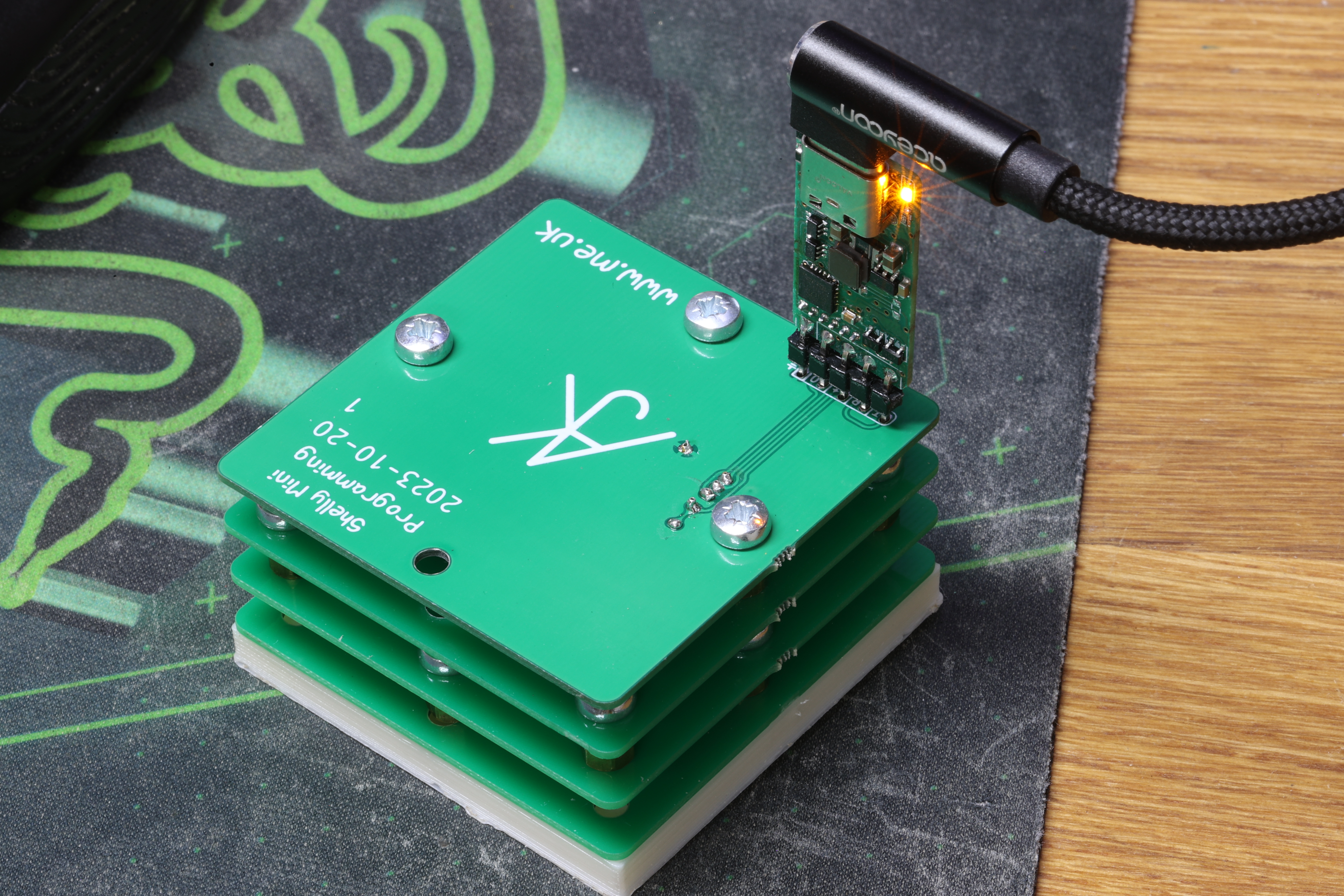
If you have not encountered Tasmota before, do take a look. It is free open source software that runs on most of these smart switches and devices. It means re-flashing the device, and they vary in complexity from "having a header you can just plug in to with a serial lead", to "soldering bits of wire inside the switch". But once re-flashed they can be re-configured and re-programmed over the air (WiFi). As for actually flashing the code - you just need a simple serial lead and the tasmotizer app, and it is very easy.

The key thing about Tasmota is that it works using a simple standard called MQTT. Having an MQTT server in your home is cheap and easy, and can integrate with various home automation systems. It does not, then, rely on any Internet connection or third party servers. It can work with various home hub / automation systems as well.

Some options

The main three options I would consider are these. All can be flashed with Tasmota.

  • Sonoff basic: This is a neat, very cheap, in-line, 10A switch. It has live/neutral one end, and switched live / neutral the other. It has a tiny button and LED as well, which are not that useful. The main downside I have found is they have a tendency to die after a while.

  • DS-102 light switch: There are a lot of these type of smart light switches. The key thing with this particular model is that it has actual tactile micro switches behind the buttons. There are many that are capacitive, so harder to work in the dark when not looking. Some also have LEDs you cannot control. But the DS-102 seems about the best I have found so far. They come in one, two, and three gang, and as mentioned they have an option for live only, supplied with a capacitor to fit across the light fitting. One big down side is you have to solder wires to re-flash them (though people have made rigs with pogo-pins to do this).

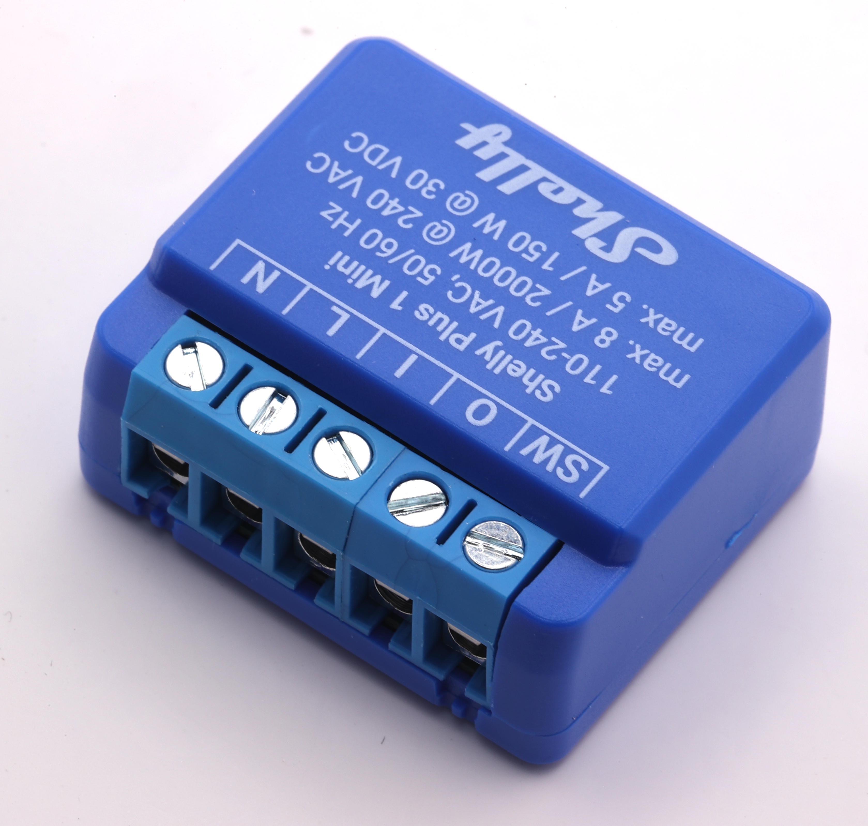
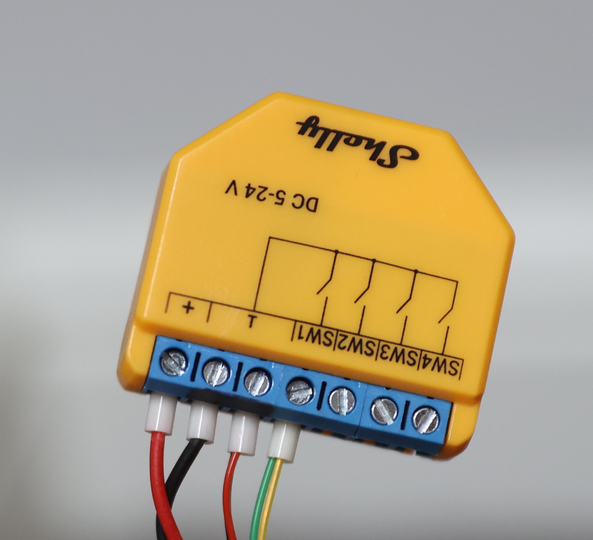
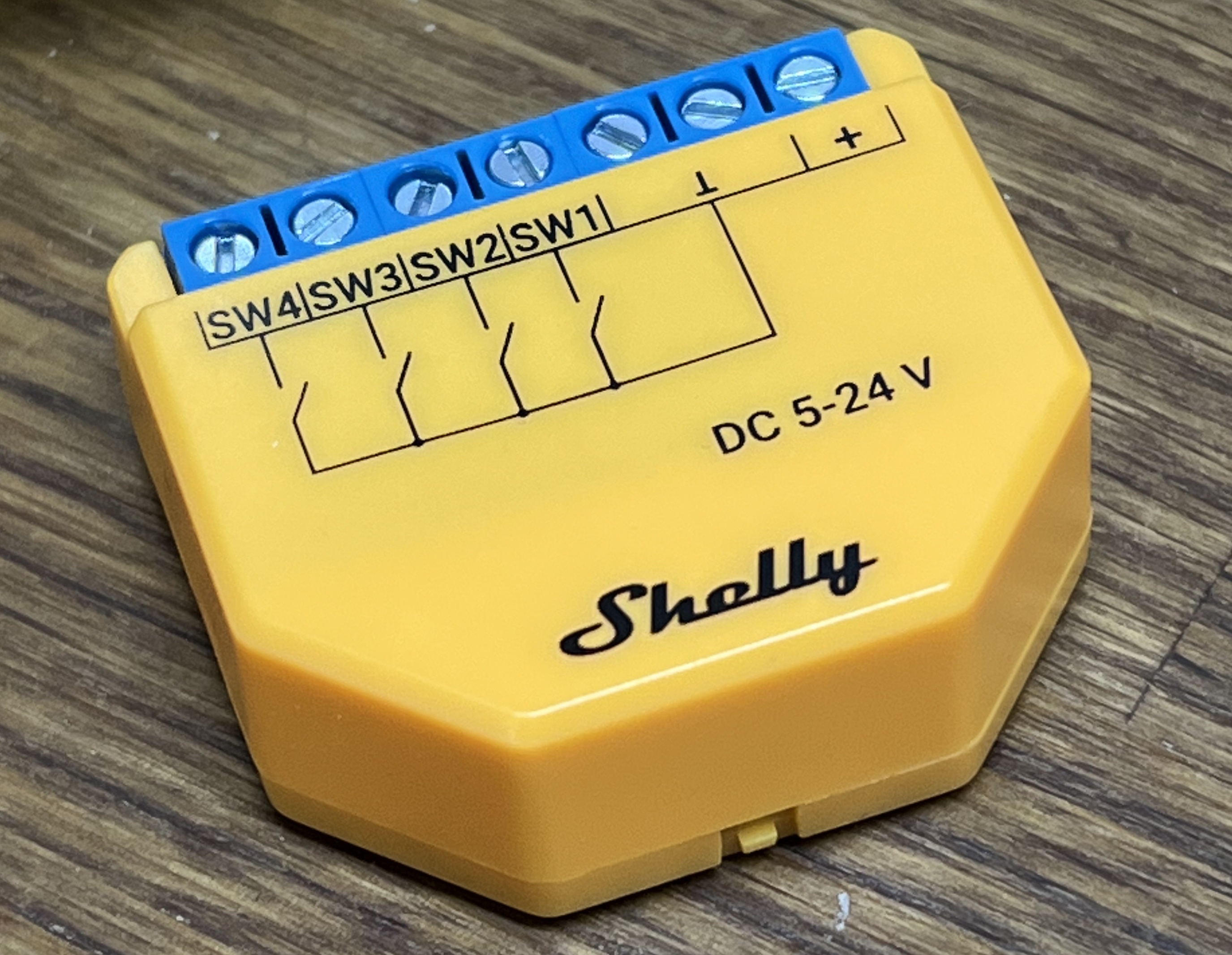
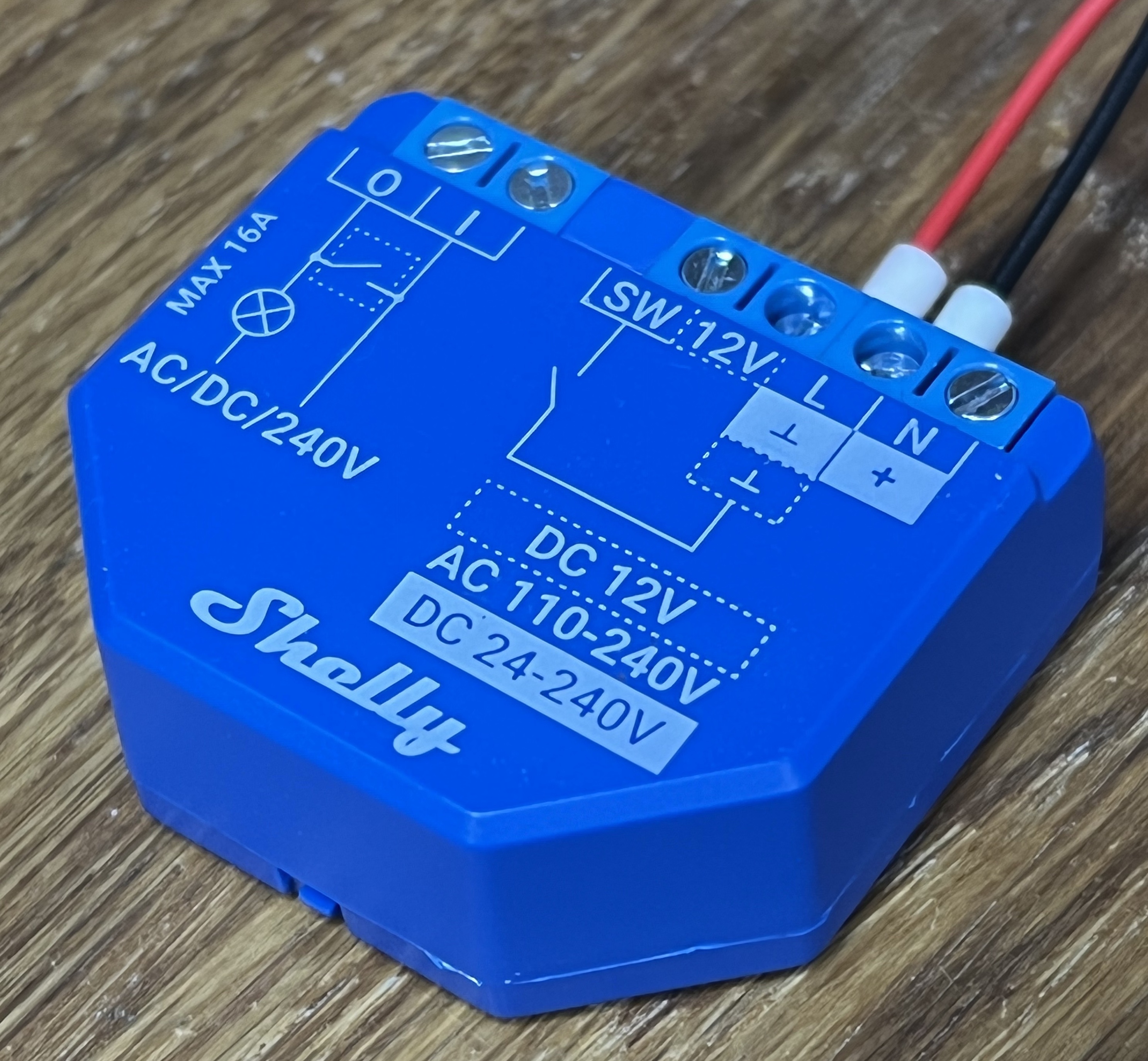
  • Shelly 1 relay: This is what I have been waiting for! It is a relay, like the sonoff basic. It costs more than the sonoff basic, but typically less than one of the smart light switches. See below.
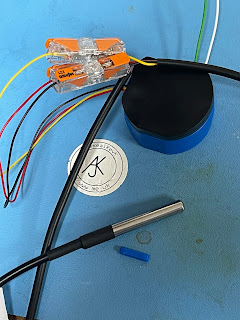
The Shelly 1

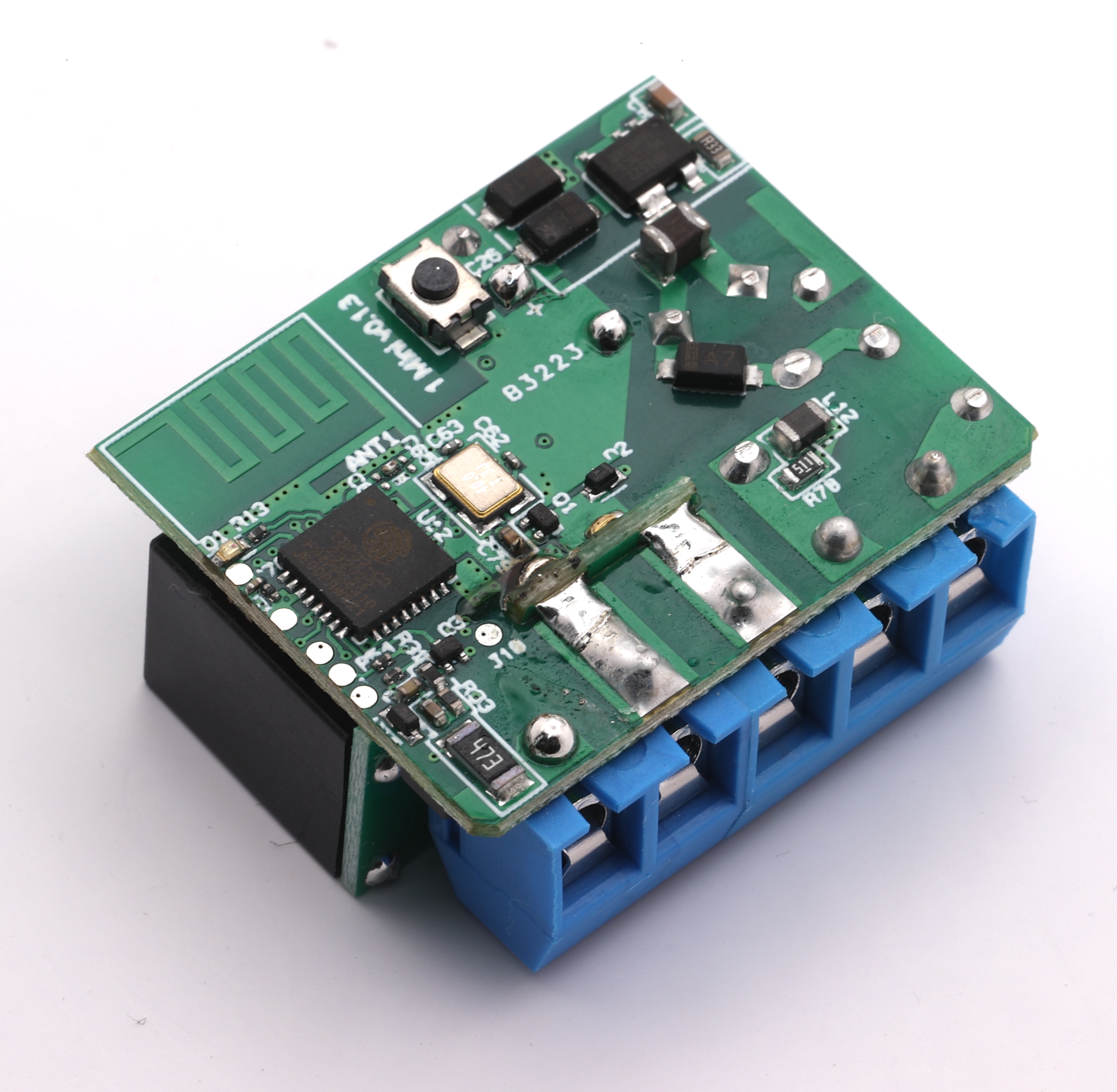
I have been after this for a long time - I even considered making one myself - something simple like the Sonoff Basic, but with a proper switch input. The Shelly 1 seems to be ideal for light controls in the UK.

It can go behind the light fitting in the ceiling where the live and neutral are already present, so solving the fact we don't have neutral at our light switches. But it can take the switched live as an input. Obviously it can have a default mode of operation where the switch works the light, so even no Internet or WiFi does not stop it working in the obvious way.

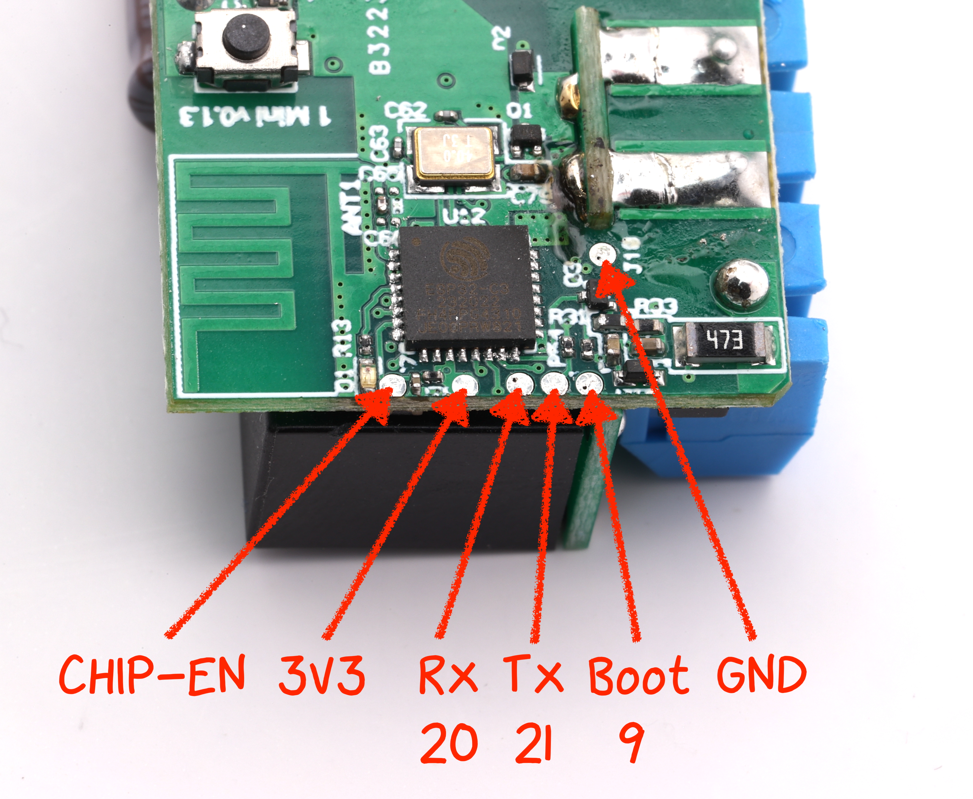
It has a simple header for re-flashing (please do take note of the warnings about these being at live voltages when connected to power!). So loading Tasmota is a doddle.

This means that with no extra wiring, and no changing to a deep back box, and no change of light switch to something cheap and tacky white plastic. It is easy to make a normal light fitting WiFi connected.

It is also 16A not 10A, so much more useful than the Sonoff basic (obviously for things other than lights, which get nowhere near that rating).

I have one coming today :-)

P.S. For those that have not used tasmota, you can have an input as a button or a switch. A button works toggling an output on pressing the button. A switch toggles the output on change of input. So a normal light switch would be connected in switch mode, and turn on/off when changed. If you override via MQTT you simply swap the way it works, much like a normal two-way light switch arrangement, so the switch now works in reverse until you next override.

P.P.S. Smaller than I expected - this is really neat, and can even run off 12V or 24V-60V if you need. This is exactly what I wanted!

P.P.P.S. I had not heard of Shelly before, but they have loads of cool stuff, all looks quite sane, including the simple to re-flash header, and the fact they will do MQTT anyway. Very cool. shellystore.co.uk

(Do always follow local electrical safety regulations, please)

2019-04-04

Tasmota / Sonoff - two way light switch controls

One small thing I wanted to do is make one Sonoff light switch work another - a simple two may light switch arrangement, such as top and bottom of stairs, etc.

Obviously, one can use a home automation server like home-assistant, but I am trying to keep it a bit simpler at the moment. I have an MQTT broker (actually on a Pi) and that allows any of the MQTT devices I have to talk to each other. Some devices, like my door entry, and alarm system have a means to send a series of MQTT messages on various events already.

It seems Tasmota / Sonoff can do what I want, but there were a couple of challenges, and reading some blogs I see I am not alone. So here is what I found and what is a gotcha or two.

The set up

What I was trying to do was have a light switch that controlled another - a simple two-way light switch arrangement (which is what it used to be). Either light switch ("button") when pressed would toggle the light, simple. I had another case where I wanted one button to control 4 lights, but we'll come to that later.

ButtonTopic

The simple answer is to set the ButtonTopic on the extra switch and tell it that the topic to use is the first switches. This should just work. But...
  • You cannot set the ButtonTopic if you are sending a group message, which it thinks you are if the name of the GroupTopic is a substring of the Topic of the device, which is just silly. The result is a status saying ButtonTopic is still "0". No error, just confusing. I had to read the code to find this. I had Bed1LS as a GroupTopic and Bed1LS3 as the device Topic. As a result I could not set the ButtonTopic to anything!
  • I don't think you can use the ButtonTopic if it is set to the same as the device GroupTopic (from looking at the code). So even changing GroupTopic and changing back to set ButtonTopic would not work in the above case. I am not totally sure why, unless it creates some sort of loop, but I cannot see why it would and it would be better to fix that than to silently ignore it.
  • You can only set a system wide ButtonTopic, not a topic for each button if you have several buttons. This is OK on a simple button switch, obviously.
  • You set the ButtonTopic just to the name, without the cmnd/ prefix or /Power suffix. It adds those - which was not obvious.
  • Note, ButtonTopic replaces the normal relay operation unless MQTT is not available.
Request: Please can we have a ButtonTopic1/2/etc for each button?
Request: Can we please avoid the loop or whatever stops use of the GroupTopic as ButtonTopic?
Request: Why is grpflg set using strstr hence meaning it is set when talking to a device where group is subset of device topic. I can see group being subset of device as quite common?

Rules

Rules are another good way to do things and are mode flexible. You can make a rule so that pressing the button publishes on MQTT. You can have more than one sequence on a rule.

You simply send something like :-

 cmnd/Bed1LS3/Rule1 on Button1#state do publish cmnd/Bed1LS/Power1 TOGGLE endon

And you can add a second part to the rule, e.g.

 cmnd/Bed1LS3/Rule1 +on Button1#state do publish cmnd/Bed1LS/Power2 TOGGLE endon

I had to add two parts because the lights switches where double, and so needs Power1 and Power2 set.
  • It looks like the Rule and ButtonTopic do not work together which is odd.
  • I could not publish a command with spaces in it, such as Backlog (to change both Power1 and Power2 together). Maybe there is a trick to that. Hence I had two parts to the rule.
  • Note, a rule on ButtonX replaces normal relay operation. A rule on PowerX happens when power changes which could be because of normal button control of power. You can test Power1#state=0 and Power1#state=1 if you don't want to use TOGGLE.
Request: Can we have it so Power (rather than Power1 or Power2) applies to all power controls so that one message could toggle or control all lights on a multiple button light switch?
Request: Can we publish something with spaces in somehow?

However, end result is good :-)

P.S. You cannot turn off the relay/button LEDs on the T1 (light switches) sadly.

Update: You can use Backlog in the command, which works well. E.g.
cmnd/GardenLS0/Rule1 on Button1#state do Backlog Publish cmnd/GardenLS1/Power 2;Delay 2;Publish cmnd/GardenLS2/Power 2;Delay 2;Publish cmnd/GardenLS3/Power 2;Delay 2;Publish cmnd/GardenLS4/Power 2;Delay 2;Publish cmnd/GardenLS5/Power 2;Delay 2;Publish cmnd/GardenLS6/Power 2; endon

Update: Be careful with now code and settings. I turned on Home Assistant Discovery and it changed the topics. I turned on WiFi signal scanning and somehow managed to put most of the sonoffs in a mode where they could not connect to the WiFi so went in to an AP mode for 3 minutes and tried again. It meant all my devices vanished and did not come back for quite a while. Several devices even somehow went in to a mode where they acted like the original SonOff code. I had to actually unscrew 4 of them and refresh, and two of those I had to erase the flash with a separate binary. The other two I had to sent a command over serial to Reset the config. So top tip: Always have one separate unit on which to test any changes first.

2019-03-25

Reprogramming a light switch

I started in computers in the late '70s when my high school got an RML 380Z. I never imagined I would ever be re-programming a light switch. Yes, a light switch, and one that is only £14.99 from amazon.

But yes, that is what I am doing. I was very impressed with this youtube video with step by step instructions on loading the Tasmota code using a Mac. It worked exactly as expected. That never happens!

I purchased a serial adapter from Amazon (here) which came with leads, and a simple molex header. The good news is you don't actually have to solder a header in the holes, you can just hold it there whilst programming. You only ever have to do this once (per device).


I now have a web page I can use to control it and configure it and so on. I had to do very little tweaking to the config, but was able to set up so it connected to the right SSID by default. I can even upgrade the s/w over the air (web interface). Impressive.

The only complication was the T1 (light switches) which needed more messing to get in to flash mode (see here). But you only need to flash once like this obviously and it is pretty simple.

Note: one other issue - edit the my_user_config.h and turn off some things you don't need (add // to start of the #define line). Test compiling Sketch->Verify/Compile to confirm under 500k size. This means you can have two copies in memory and hence upgrade the firmware over the air via its web page. If not, you have to take apart and re-flash to change code.

Next step MQTT... This is the messaging broker used to control and report button pushes...

It seems a simple apt install mosquitto moquitto-clients is a good start. And just like that I have an MQTT broker just working. Wow. Running in debug shows the events and everything, but it just works.

By setting the MQTT topic on a device, in this case to pixar, I can do commands like mosquitto_pub -t cmnd/pixar/Power -m 1 to turn the lamp on!

It allows me to send commands to the sonoff devices, and allows me to collect messages from them - cool. Next step I expect is to set up some scripts to do what I want.

That, or play with something like home-assistant.


P.S. I did tidy the wiring - the cover now clamps on the sleeving as it should.


QR abuse...

I'm known for QR code stuff, and my library, but I have done some abuse of them for fun - I did round pixels  rather than rectangular, f...