2022-02-28

ESP32-PICO-MINI-02

I started playing with Espressif processors with the ESP8266, and quickly moved to the ESP32. The main module I have been using is the ESP32-WROOM-32. Using a module avoid having to mess with RF directly, and makes it a lot easier.

However, I have now discovered the new ESP32-PICO-MINI-02 module.

It is quite impressive.

  1. It is smaller, half the size of the ESP32-WROOM-32.
  2. It has more flash (8MB not 4MB, though WROOM modules can have more).
  3. It has SPI RAM (2MB) so a total of 2½MB RAM rather than just ½MB. Impressive.
  4. It cannot be hand soldered as pads underneath the module.
  5. Did I say it was tiny?

How is it so small? Well, unlike the ESP32-WROOM-32, which is several devices in the module (the processor and a flash), it is all one chip. They have integrated the flash and SPI RAM all in one device.

So, armed with this impressive new chip, I have been playing around with my various designs. Re-designing a board to use this is simple at the schematic level, but more of a challenge when it comes to layout. The good news is I am better at layout now, and doing a board a second time is easier, so I have managed to make all my various designs much smaller. This is quite helpful for things like the alarm system controller which has to fit in an EXIT button back box, and can be a squeeze, or even the Galaxy keypad controller than fits in a small gap in the case.

I have taken the chance to tidy up my designs a bit as well, lower power when not using USB, by turning off the USB controller, etc.

I have also designed to make some more boards - including a small generic module, using this:-

This provides 10 GPIO pins, but is a tiny board. I've also made a GPS board.

I was obviously a bit worried about a new module - did I read the data sheet right? Can I solder it (using solder paste) properly? Well I am pleased to say, it worked first time. Yay!

Update: The GPS module works as well. It is fun as has a few GPIOs not normally on the WROOM module (7, 8, and 20). It is worth noting that it uses an ESP32-PICO-V3-02 chip, the V3 and 02 all make slight differences, so worth checking data sheets carefully.

2022-02-10

And another board

And another board, just works.

One of the designs I made a while ago was a very small "generic" ESP32-WROOM-32 module. It had a 6 pin connector (normally a SPOX 2.5mm, but can be 0.1" headers). It was GND and 5 GPIO pins. It really was tiny, and has proved very useful.

But occasionally I need more pins, and a full size general dev board is much more bulky.

So I made a Mk2 that is a bit bigger. 2x8 pins, all of which can be GPIO. By default one each side is GND, and the next ones can be linked to DC supply or 3.3V. 6 of the 8 have BAV99 diodes for ESD protection as well. The whole thing can be powered from DC contacts (4V-40V) or a USB-C lead. The USB does serial to make easy to load code, and there is an RGB LED as well.

It is still pretty small, but a bit more useful.

2022-02-07

The new ASR33 controller board

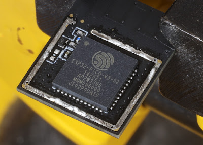
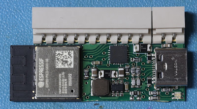
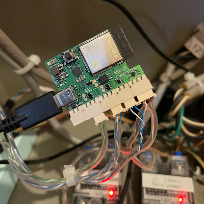
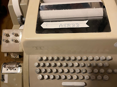
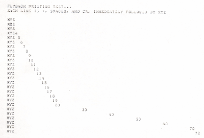
My nice shiny new ASR33 controller boards arrived today, and I am really pleased to say it worked first time, and is now running my teletype.

My previous approach was to use a more generic ESP32 board. Indeed, I used a simple dev board for my first attempt, and then a smaller generic board I had made. This did work, mostly.

To send to the Teletype 20mA I was able to simply use a resistor to limit current to 20mA from a 3.3V GPIO line. The ASR33 has a transistor input, so that actually worked well.

The receive side should be simple - the teletype just makes or breaks a circuit. So a simple pull up resistor and then the teletype loop grounding a GPIO pin. Well, should work, in theory.

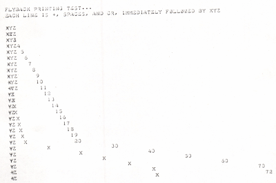
Sadly it was never good. It depended massively on the distributor with carbon brushes, and leaf contacts, and was, shall we say, flaky. Yes, if you exercised the distributor (hold REPEAT and RETURN) for a while, it would clean up enough to work most of the time, but still not 100% reliable. Looking on a scope it was clear why it was so bad - the signal was just horrid.

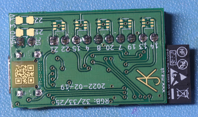
The solution is a completely new dedicated ASR33 controller board.

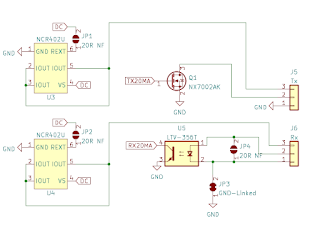
The first thing I did was to find a suitable 20mA source. I picked the NCR402U constant current source designed for LEDs. It defaults to 20mA but has an option of a resistor to change this. This also has the advantage that it can run off a higher voltage if needed, though the ASR33 does not need that. I needed two of these, one for Tx and one for Rx as the ASR33 is passive on SEND and RECEIVE sides.

For sending, I then used a simple FET to connect the signal to ground. This means I have a 20mA source out, and a return which connects via a FET to ground, and causes 20mA to flow. The result is very clean, and drives the teletype nicely. But, as I say, just using a simple resistor off a GPIO also worked.

For receiving, I originally tried the 20mA via the teletype SEND circuit, and to a resistor. This should give me a simple voltage on a GPIO pin which relates to the current, 20mA or open circuit. It should be simple. But no, just as noisy as the original solution. The fix was to fit an optocoupler. The 20mA source goes via the teletype SEND circuit and then through an LED in the optocoupler. The output then goes in to a GPIO with an internal pull up. This is clean. Very clean indeed.

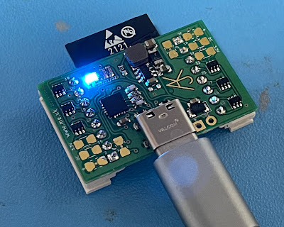
The result is both Tx and Rx working perfectly. I am very pleased with the result, and it makes the whole teletype much more usable.

Passive or active?

The ASR33 is passive for SEND and RECEIVE, but some teletypes could be active, so for that reason the Tx site FET can be used without the current source, and similarly the Rx optocoupler can be connected without using the current source.

I also added pads to allow a change to 60mA. However I don't have a 60mA teletype, and they typically drove a selector solenoid directly. That will not work from the 5V USB, and the board can only really do 40V which is unlikely to work even if at 60mA. Something to try when I send a board to someone with such a teletype.

More than just Tx and Rx?

The only standard connection on the teletype 20mA loop connections for Tx and Rx, but you usually want a little more. In this case a power control. I used a simple solid state relay to control the power to the whole machine, driven from a GPIO pin. But I also coded use of MQTT to work an external power switch running tasmota if needed. This allows the teletype to turn on, do something, and turn off, nicely.

Sadly having motor start at the same time is a problem as you get duff characters clocked in. The answer to this was fit an extra lead in to the teletype to allow the motor's power to be switched, using another solid state relay. This means the motor can start and stop while the power is still on, and ensure a clean start and stop without a duff random character (it actually clocks a non printing RO character).

But there is more ... if the ESP32 is controlling power, you need a power switch. For this I have one more GPIO to go to a button. My teletype has a MOTOR START button from an original, and more complex, motor control circuit. This was bypassed and run to the controller to allow it to be used to power on and off.

Of course I also have a multi-colour LED and a button to force a config more (WiFi AP and simple setting page to set WiFI and MQTT details).

Why?

The basic purpose is to allow a teletype to connect via a simple TCP socket. This makes it a lot easier to work with any modern computer system than an actual serial lead.

But it also does a few other things, a local echo, an punching large text on paper tape, and even a game of colossal cave built in. I mean why not?

CR+LF has a long history...

The ASR33, like most teletypes of the era, works at a fixed rate. It does 10 characters per second. It is 110 Baud, using 1 start, 8 data (inc parity), and 2 stop, so 10cps Tx and 10cps Rx; 10cps printing; 10cps punching tape; 10cps reading tape; 10cps maximum typing speed. Everything happens based on one motor that does this 10cps working, engaging clutches to start an operation which completes in one turn. So everything has to happen within 100ms, well, sort of.

There is one exception: carriage return [CR]. The carriage is released within the 100ms time, but the carriage is on a spring, and does not get back to the left within 100ms if it is too far over to the right. The usual fix is to send another non printing character, such as a line feed [LF], as the next character, where CR and LF are used for each new line. The paper advances whilst the carriage is returning so giving the carriage a whole 200ms to complete the return. This allows enough time to get to the left, but can leave the carriage still bouncing and mean the first printable character is not well aligned. The fact that 200ms is enough is usually fine, unless you are particularly fussy. The fix to this is to send another non printing character, such as a NULL, another CR, or even a rub out [RO]. The standard HEREIS drum coding even specifies CR, LF and RO at the start.

If you do send characters immediately following a CR, you get them printed in the fly-back of the carriage, like this...

The whole “new line = CR+LF” thing has plagued computing for the last 6 decades, with some systems and file formats using CR as new line, some LF, and some CR+LF. Even today I can find I have a file in DOS format using CR+LF that needs converting.

The software I have written in the controller allows for this when printing text itself, doing CR, LF for new line, and adding a NULL if beyond 40 columns at the time. This works, and is used for prompts and even the Colossal Cave game that is built in.

However, this presents a few issues :-

  • This works when generating text, but if in some sort of raw mode it mean the sending device needs to know to do this. Some systems know, some do not.
  • If this is done automatically, so extra characters are inserted that is not a problem for printing, but for punching paper tape it records those extra characters. That said, a NULL or RO on paper tape should not normally be an issue when read in. But it is not ideal, and assumes it is not binary data on the paper tape for some reason. So you sort of need a raw or processed mode for handling such tape, which is messy.
  • Paper tape is sometimes used for raw / binary data, but can also be used for “large text” or patterns (which is gibberish as printed). Whilst fun, this also has a practical use to label reels of paper tape at the start in a human readable format. If automatic extra characters for CR handling are added, they mess this up.

A new solution to an old problem...

My solution works because we are now using a soft UART. I am doing this, working the individual data bits on a timer interrupt, to allow the extra low Baud rates used by some teletypes, which are not supported by hardware UARTs. Some work as low as 45.45 Baud even.

The soft UART has now been coded so that the bytes, as actually sent to the teletype (i.e. not when buffered/queued, but in real time), are tracked to know carriage position, and operate a timer between sending a CR and the next printable character. A non printable character like a NL, NULL, RO, are allowed within this timeout, but the timeout has to finish before the first printable character after a CR. This allows the CR to complete and avoids printing a character during the fly-back of the carriage.

This means :-

  • Where the sending device is sending the extra characters, even just a CR, LF, to allow for CR, then the operation is totally unchanged. This makes it 100% backwards compatible with existing working of teletypes and means no special raw or processed modes needed.
  • Where the CR needs this extra time it can be done in sub character, even sub bit, periods, not wasting the time for a whole extra character such as a NULL.
  • The delay can be adjusted for the position of the carriage, and hence allow just the time it will take to complete the return.
  • This works even when CR is immediately followed by a printable character (causing a pause you can just hear on longer lines).
  • No extra characters are actually inserted, so characters as punched on paper tape are perfect, no gaps or ROs, etc.

This works well, even with a printable character immediately following the CR, like this...

Today I learned...

What is funny (well, for me) is that there will be people who have worked in computing and IT for decades and encountered the whole craziness that is CR and LF, but have no idea why it was ever a thing. I hope this, in some way, explains some of the background.


You're welcome :-)

[thanks xkcd]

P.S. I cannot say for sure that the way teletypes work is why CR and LF are separate. They were around at the time ASCII was being developed - heck my teletype does not even have lower case as it is 1963 first ASCII version. So the way they work is quite likely to be a factor. That said, CR and LF as characters dates back even further than ASCII. It is true that CR being separate has been used for things like over printing underscores, even over printing hyphens many types to make a perforation, and other tricks, but I suspect those tricks are all a consequence of CR being separate and not the reason for it. Even the older manual typewriters would have a manual carriage return level that would typically do the line feed at the same time - so it seems odd they would be made separate characters if not for this reason. It is odd how, what may have seemed trivial at the time, such a decision still impacts computing today. At the very least, you can see why it is CR then LF, and not LF then CR, in files.

2022-02-04

So this £200 loan will be mandatory - crazy!

Yep, it seems this £200 loan will be mandatory. Crazy! 


(P.S. impressively prompt reply)
And seems people are concerned (one of my most liked tweets)...

Missing unix/linux/posix file open option

What I would like is a file open option for "create replacement file". The idea is that this makes a new inode in the same mount p...