2023-12-28

Ordering PCBs

Ordering PCBs and assembly is fun :-)

Well, not fun, and to be honest, one of the biggest challenges is the parts selection, what they have in stock or something equivalent, but designing the PCB is definitely fun (well, for me).

I export a gerber files that are the instructions to make the PCB tracking images, and also a BOM (bill of materials) and position file, for placing the parts.

I have done this many many times with several PCB manufacturers, and lately with JLCPCB, which seem to be surprisingly quick and sensibly priced (apart from the odd quirk). I'd love to find a UK company as cheap and easy to use, I'd use them.

The PCB printing has a few design constraints, the gaps between tracks, minimum track width, and so on, which relate to the optics of the process for printing and drilling the board itself. But apart from that the PCB is printed exactly as expected.

Well, until now.

This is what I ordered... (this is an image from their order history page)

And this is what arrived...

It took me ages to debug it - tracking down that the CPU was running way too hot (burned my finger) and not quite right. It turned out it was running on 4.5V not 3.3V. The shorts there short input to output on a regulator circuit and I was testing from 5V USB via a diode. If I had tested 12V it would have made smoke, I expect.

The thing is the order process involves a lot of steps, and each step show the PCB you are making.

  • When uploading the gerber files
  • When selecting assembly and it shows the bare PCB
  • When showing PCB with parts
  • When order complete and preview of PCB
  • When order complete and preview of assembly
  • On gerber viewer on the site from their order confirmation

At every stage they show the circuit correctly, but the final PCB was faulty.

I complained, and they advised: "We have reflected this issue to our engineering team and JLCCAM software team and they have found and fixed the issue just now, and there will be no the same issue next time, so don't worry about it."

They even provided an image of the error:

Next step - refund!

My view is simple.

  • They made an error in printing the PCB.
  • Arguably they made an error with the flying lead test of the PCB not spotting the printing error.
  • They then made the PCB with parts that cost money - either of the above errors not made would have avoided that.
  • It was not, in any way, my fault.
  • I did not get what I paid for.

It is simple. I should not only have a full refund, including shipping cost, but ideally I should be compensated for the hours of debug, the delay in getting working boards, and the cost of disposing of the WEEE (defunct PCBs and part).

I'll be happy for just a full refund, and either they pay for courier to return boards, or I dispose of them (at my cost). As I buy loads from them, I'd even allow for it to be a credit on my account rather than an actual refund.

I have a funny feeling they will try and weasel out of this - and then I may have to ask Amex to intervene. It is for two separate batches of boards (from 4 I ordered, 2 of which were fine) totalling over $470.

Watch this space - I'll update with news.

Update: They do seem to be trying to weasel out of out - that PCB manufacturer is separate from supplying parts and assembly - but the parts they supplied are useless to me as supplied, so not reasonable that I pay for them, surely? Indeed, I have offered to send the parts back to them (at their cost). We'll see how that goes.

They suggested I try and isolate the track, but this is cutting through soldered pads, so when I put the components back it will short again!

Update: They are being counter reasonable. I suggested I could maybe find someone to rework - they suggested I try, and get a quote. I may try and get a quote.

They also think just cleaning solder would be enough to avoid shorting with the component leads when cut like this...

Update: I have decided instead to offer a compromise on basis that on one board I can re-use the SCD41 sensors they have supplied. Pushing their offer $50 more on each set of boards. We'll see.

Update: We have credits now.

2023-12-17

Rule 170

The Highway code Rule 170 was updated a while ago. Last time I posted about it was before the update, and was surprisingly controversial for some reason. This time I hope less so.

The changes

The changes were actually quite subtle, in my view.

1. It used to say that pedestrians crossing a side road had priority over vehicles entering the side road. It now says that drivers should give way to pedestrians waiting as well as crossing. I say this is subtle, as, before, a driver had to allow for the fact that a pedestrian waiting could become a pedestrian crossing in an instant by putting their foot on the road.

2. Pedestrians used to only have priority half way, i.e. over vehicles entering the side road. Now the rule covers cars leaving as well, which was a silly omission before.

The main rule

The key rule here is "give way to pedestrians crossing or waiting to cross a road into which or from which you are turning. If they have started to cross they have priority, so give way", but it is worth noting the first part "watch out for cyclists, motorcyclists and pedestrians including powered wheelchairs/mobility scooter users as they are not always easy to see. Be aware that they may not have seen or heard you if you are approaching from behind"

Going well

I think the change is working!

I suspect the publicity over the change has had most impact rather than the change itself, as drivers used to ignore the old rules, in my experience.

I used to see a lot of cases where a car turning right in to a side road would wait for traffic and then turn, even though I was crossing said side road. They then slam on their brakes and get cross with me. It seems they thought I should see them signalling and wait. Obviously I could see them, but as (a) they are stationary, and (b) I had priority, then of course it should be safe for me to cross.

I am seeing this less, and I am even seeing cars coming to a main road stop with a gap to allow me to cross in front of them. Obviously if they stop on the line I just cross in front of them walking on the dotted line. This brings the other concern I have over the number of drivers that will pull away without looking to see if someone is right on their bumper in front of them!

Clarification

I like clear wording if possible, and I feel the new wording has a couple of possible issues where it could be improved.

I would hope these are silly niggles and any driver would be clear on what they should do, but given the lack of understanding so many drivers have, and the controversial comments on my last post which revolved around very specific wording, I can't help feeling the wording could be improved.

Crossing or waiting?

The rule covers pedestrian crossing or waiting to cross, but seems to be to have a glaring omission. A pedestrian assertively walking towards the edge of the road with the clear intention of crossing, i.e. no indication of stopping. In that case they are neither crossing, nor waiting to cross.

I feel a simple change from waiting to "intending to cross" would cover this loophole.

Turning

Another oddity is the use of turning. If you have a cross roads, two side roads on a main road opposite each other. Cars may be leaving or entering a side road from the other side road with no turning involved. Using words entering or leaving would clarify that stupid loophole.

Driveways

I don't think it is controversial to say that cars entering or leaving a driveway should give way to pedestrians, and I suspect it is covered elsewhere by the fact the car is crossing the footpath itself. So probably does not need clarifying in rule 170 itself.

Private Roads

I would hope rule 170 applies to private roads, e.g. entrance/exit of supermarket car parks, etc. These do not always have the usual dotted road markings. It would be nice if rule 170 actually made this clear. I have seen plenty of drivers seem confused that I am crossing in front of them whilst they are waiting to leave a car park.

However, apparently any private road to which the public have access is a "road" under law, so it would apply.

Roundabouts

This is one I have no clue on - does rule 170 apply to the exits of a roundabout.

As a pedestrian this would be very useful. As worded, surely leaving or entering a roundabout is turning in to a or from a road. So rule 170 should apply. Or is a roundabout not a junction, so rule 170 does not apply at all?

So does it? It would help if rule 170 was clear on this either way.

Turning in to a road

Another odd one is when are your entering or leaving a road. E.g. in the middle of Abergavenny there is a sharp turn between Cross Street and Monk Street. So vehicles are clearing turning in to a new road. But both are the A40, so are they? And is it a junction? The particular turning is marked as a box junction so surely it is a junction, so the only question is whether going from Cross St to Monk St is turning in to a road? It would be great if pedestrians did have priority there, and if they do, it may be possible to get the road authority to put of a sign of some sort - they refuse to put in a zebra crossing for some reason.

More law

This blog is excellent! https://pedestrianliberation.org/the-law-2/

BACS and Direct Debit

10 years ago I posted about us having to re-do our payments system with only 2 months notice. That time was because of HMRC making changes that caused Lloyds to very suddenly close their BACS bureau. Scary times.

Last month we got two months notice that the BACS submission system we use (Experian) was end of life. Do these people have no clue how slow banking stuff moves?

So, the good news, my management team (Alex/Andrew) investigated a number of solutions. Most would stand no chance of being up and running in the time frame. But of a couple of options could be: one was by the company doing the Experian s/w (they took them over!) which could magically "support" the Experian system after "end of life" if we are onboarding (horrid word) their new system.

However we picked someone else - InterBACS, who are clearly technically clued up and have allowed us to get working very quickly.

What are BACS submissions?

There are two main reasons you want to send files to BACS, one if Direct Debits (getting money from people), and one is Direct Credits (paying people). Direct Debits actually have special messages for setting up and cancelling Direct Debits as well as the actual payment connection messages. These type of direct credits are usually for payroll and is the older system, not to be confused with Fast Payments. Either way the process takes two banking days, and then the money moves. A reliable system. There are also a load of BACS reports we have to get, which include reports on the submission, and on changes to Direct Debits by banks, people moving to new banks and accounts, errors, bounced Direct Debit collections, and clawed back Direct Debit payments. These can actually be downloaded from the BACS web site.

Three ways to make BACS submissions.

It looks like there are three ways to do BACS submissions (and get reports). I thought there were only the first two, but we discovered InterBACS do a third way.

1. Bureau

One of the simplest ways is dealing with a BACS bureau - they accept a file from you, and authenticate you by whatever means they agree, and they send the file to BACS for you.

In most cases they don't actually take a "file", but "manage" Direct Debits for you, so you tell them a new customer, and how much they are paying every month - they then send the notice to the customer, and do the payments, and so on. This is ideal for a gym or the like, and can mean a simple web interface to manage regular customer payments.

2. Direct submission

For direct submission you have software to send files to BACS directly. This is what we had with the Experian system. It means we have a BACS user and smart card from the bank. This is used to sign the submission file, and to log in to BACS (to send the file and get reports). The signing code only works on windows, which is a tad annoying - the only windows machine we have. This is usually cheaper than a bureau.

3. Web based direct submission

This was new to us, and what InterBACS do. They have a web based system, allowing us to upload a submission file to them. Then, via the web page, log in to BACS - they log in, but they have the web browser (or a separate app depending on the browser) do the signing for the login using the card signing and card on our windows machine. So it is logged in, remotely. Similar they do signing the submission file remotely using the card on our windows machine. They get BACS reports and allow us to download them. It means we don't have to install BACS software, just the card signing stuff from the bank, and use a browser.

The also have a bureau service, and also have a whole management package for people just wanting to set up monthly payments, etc.

HSM

There is another option, but very expensive. The bank could provide a hardware security module certificate, which we either have an (expensive) HSM, or have the certificate loaded on InterBACS's HSM. This allows the whole logging in to BACS and signing the submission without a manual use of a card and PIN. I.e. it can be fully automated. Sadly it is way too expensive to be remotely viable.

Experience with InterBACS

We picked them as they seemed clued up and very responsive. They were very quick to sort things out and the whole thing just works. So quite impressed.

Also, they were responsive when we needed minor changes - a bulk save of all reports rather than selecting each one, etc.

We are now up and running with them in only a few weeks. Indeed, in hindsight, it could have been under a week, had the deadline been even closer, but we were a little cautious with lots of testing first.

2023-11-28

No No-bell prize

I wanted to improve our doorbell... Yes, that is dull.

But the main change is not the bell (a nice, old style bell in the kitchen, which is driven by a Shelly, and the sitting room, and flashing lights in bedrooms and hot tub), or the bell push itself as such, but a sign on the door by the bell.

We used to have a simple brass "please ring the bell" sign, pointing to the bell push. Still, too many people knock instead.

Push the button

So the idea is a sign, and additional bell push right by it, on the actual door. The sign has the house name and number and road name - that itself may help as we get parcels for the same number in the next road often, and they get ours. But a sign saying ring the bell with a hand pointing to the bell push right by the sign.

The magic happens when they push the bell (either the new or old bell push) - the sign lights LEDs on the back and changes. The basic option is like this...

I included a barcode with date time and postcode for photos when leaving a parcel.

Seasons greetings

I also decided it may be a fun idea to change the message, add Christmas tree for now, and so on, but even regionalise the message...


The idle message can be updated and made seasonal, I may even automate based on date, but also the message shown when you press the button can vary depending on circumstances. This saves me putting a sign on the door when we are out - which is a notice to everyone that we are, well, out. The message for when we are out ("leave parcels behind the double gates") is only shown when someone pushes the bell. Indeed other messages can be set if needed.

Let there be light

The main way it decides what to show is based on lights. Yes, that seems crazy, but is incredibly simple when almost all lights are Shelly running tasmota and reporting to MQTT. I can track light states. I have a stairs light which only gets turned off when the alarm is set (we are out). I also track the hall light, which is an easy way I can indicate "we are busy, leave by the door" for when I am in the hot tub, etc. Indeed, if I change a light when the message shown updates in real time, so if in the hot tub I can remote turn off the hall light from my phone when the bell rings.

I also have Mastodon DMs for the bell, with exact time stamps to make easy to find in CCTV.

It also means control of the status display is something my wife can also easily understand and change if she wants, just using light switches.

Making a board

Obviously I designed my own circuit board for this. It works with a waveshare 7.5" e-paper display.


It sticks to the back of the board, has an ESP32-S3 with wifi, USB connectors, and big solder tabs for wires for power and the bell itself. It was designed so it could be set in resin even (though that seems to break the e-paper, possibly by getting in the FPC connector). So a bare board with acrylic spray for now.

No-bell prize

It did not work. The screen did not update properly. I was disappointed to say the least.

Old
New

The fix was to change the inductor and make it work, yay, no no-bell prize for me now.

So, finally, it works!

Update: The only reason this board is this size is because it has LEDs (one in each corner) do fits the 7.5" e-paper. If not then it could use a much smaller board, which I have also designed. But the new version of this larger board now has 24 LEDs, given that the LEDs are the only reason for the larger board this makes sense, but it may be a slight power issue as they are 10mA when white, so some testing may be necessary.

Update: I love the fact I have been accused of "nerd sniping" Bloor. He got one of these 7.5" panels with the waveshare HAT, and somehow he totally messed up the simple task of the FPC connectors, so much he broke several of them, and then managed to crack the display trying to get one working, and threw it all away. I come in and not only have no problem with the connectors, but then I don't just use the 7.5" panel and HAT with no problem, but make my own better PCB, and a new smaller PCB, and a version 2 of both boards, and a working door sign, and now even listing on Amazon! Is that "nerd sniping", or am I bad?

2023-11-06

USB-C Plugs, Sockets, and 5V supply

Assuming you want to use a USB Type-C connector, but just want USB2 (D-/D+) and 5V power.

So many get this wrong, however, it seems the answer is quite simple.

It would seem there are a number of connectors you can get, with just the main USB2 pins, or with all USB-C pins.

For a USB-C Socket, you need to connect CC1, and CC2, separately, via 5k1 resistors to GND. Like so.

However, for a USB-C plug, the CC1/CC2 pins are actually CC and VCONN. You connect CC via 5k1 to GND, and leave VCONN unconnected. If you connect both then it won't work! Like so.

Yes, the connector is reversible, so actually it does not matter if A5 or B5 are connected to the 5k1 resistor, just as long as only one of them is.

2023-11-01

LiPo batteries

I have done a lot of small circuit boards, but one of the challenges with any board is battery working.

I used the Watchy as a good example of this, understanding how to put the ESP32 in to deep sleep and so on. This worked very well. What I had not done until now was actually make a battery based board myself.

The first attempt, which was a massive long shot, was to test if I could run an ESP32 (ESP32-S3-MINI-1) off a button cell. The answer is no. This was not a big surprise.

So the next attempt was this :-

This has a small LiPo battery, an LDO regulator, and a charger circuit. This is basically copied the choice of components for these from the Watchy design.

There are a few things you need for battery working though - for a start, I have a FET to control power to the LED chain. The LEDs, when idle, do use very little power, but for battery working I want it to be zero power. So I have a GPIO that actually switches the power for the LED chain on and off (this is the small WS2812B compatible 3.3V RGB LEDs I have been using lately).

Another small trick is to also use a FET to switch the battery voltage to an ADC. The ADC on the ESP32 needs a lower voltage, so has a potential divider. The problem is a potential divider uses a small amount of current all the time - so again, this is switched on using a FET. I don't know if that is really necessary, but every uA helps. This should, hopefully, allow me to confirm battery levels whenever I need.

One small issue, which I have yet to quite get to the bottom of, is waking from deep sleep. The ESP32 IDF seems to suggest it is possible to make any RTC GPIO cause a wake on a state change. This is ideal for any buttons (I have two on that board design). However, that did not seem to work. I'll experiment more. There is, however, a separate way to do this, which is you can have a set of RTC GPIOs and wake on "any high" or "all low". For more than one button (I added two for the hell of it), this only really works if you have the idle state of the button low, not high. I had, as is common, had these buttons switched to GND with a pull up. I had to change the design not be reversed to allow wake on either button being pressed (at least until I get the "change of state" logic working).

I had fun finding a suitable upright USB-C connector, and I have juggled the various connector positions a bit since this original design.

Now to find what the battery life is when idle, and how many times you can use it before it goes flat. But it does work - yay!

2023-10-14

Playing with a serious number of WS2812B RGB LEDs

I have done some fun stuff with LEDs, but now I have found some very small 1mmx1mm WS2812B LEDs, I decided to make a Stargate.

Well, the doctor said to rest, so this is my resting! I have spent a week on this - much of that waiting for slightly wrong 3D prints to print. 3D printing is always a massive time hog.

My first ideas was 210 LED, but then I went for a better design with 372 LEDs.

I have since revised the design to 507 LEDs!

The image shown here is the 372 LED design.

Needless to say, some C code was used to place the LEDs and caps and vias and tracks for this.

To my surprise the power usage is not that bad, all 372 LEDs on full white is 3.6A, including the ESP32. So can run off a suitable USB charger.

In practice, the Stargate dialling sequence does not go over 0.8A, so no problem.

As usual, all open source on my GitHub.

However, I did find that JLCPCB cannot cope with more than 400 designators on one line in a BOM file :-)

As for spinning, I could make a spinning effect using 117 LED rings, but I could not spin the actual glyphs - so as a compromise I illuminate the glyphs that are dialled in situ. I think it works quite well.

Of course, the challenge then was a 3D case for it. This was tricky - there are a lot of 3D models of stargates, some more easily printed than others, but I wanted one I could nicely slice in two and allow the PCB to be inserted. That proved more complex, so I designed one from scratch in OpenSCAD. It is simplified to be easy to 3D print, even though the whole thing is nearly 7 hours print time.

I also needed a reasonably neutral colour to allow the LEDs to show. I ended up using the ColorFabb Glowfill, which has the side effect that it glows in the dark.

Here is it dialling...

This is the latest 507 LED PCB design, the main change is an extra kawoosh ring that will be inside the 100mm gate ring. The idea is that this could then work with a mirror and half mirror perhaps to make a gate tunnel effect. I'll see when I make some more. It works out around £30 per board, shipped.

The extra tabs are not a space gate effect, honest, they are tooling holes and fiducials for production, and get snapped off.


That's a lot of LEDs

2023-10-07

Shelly Plus PM Mini

Another in the Mini series from Shelly, the PM (Power monitor).

Update: explanation from Shelly: Easy, N is almost double the heat inside of the device. Sorry but in such small size we didn't want it. Double out allow to use single device in double socket which is most useful than second N.

Obviously this wants to be in-line with the device you are monitoring.

What struck me as odd from the pictures, and did confuse others as well, is that it has L/N (in) and O/O (out).

Is that L/N in and L/N out? That would make sense if it is to go in-line to a device being monitored.

No it is not!

As you can see, the O/O are both wired together and are the Live out after the monitor.

There is no second N, so wiring in this in-line either means two neutral in one screw terminal (not ideal) or a wago to join the neutral wires.


Why Shelly? Why?

I appreciate an L/N/gap/L/N may have been messy to track the neutrals, but what they could, very easily, have done have N/N/L/gap/O. This would allow live in and out, and neutral in and out and no wagos, and no two wires in one screw terminal. Way better.

I had to draw diagrams to explain to the people on the Shelly group on facebook!

How you have to wire it now

How it could have been

As explained above, the explanation is N through the device is extra heat, but to be honest I do not buy it.

The two O, meant that if one uses the second O only, all the current has to flow an extra few mm via a nice thick track to the second O terminal and that is extra resistance and heat. But surely that is exactly the same as would happen with N flowing to an adjacent N terminal the other side.

2023-10-06

Shelly Plus 1 Mini

The new Shelly Plus 1 Mini is now available, and it is indeed tiny.

Note: Detailed instructions of upgrade from Shelly to Tasmota via web interface at the end of this blog.

Key differences from the Shelly Plus 1

  • Smaller (33½mm x 28mm x 16mm)
  • Cheaper
  • No DC power
  • No programming connections
  • 8A not 16A relay

The lack of programming header was a concern as I have always reflashed these using the programming header - but it can be done via the web control pages.

I did try, and failed, to find an image of the back of a Shelly Plus 1 Mini - so here you are...

It does still have a dry contact relay, making it suitable for working DC contacts (garage door opener, etc).

It still has the button on the back.

It still has an LED in the back.

It does still have the ESP32 processor.

But overall, this is a welcome addition to the Shelly family.

Inside

The inside is indeed compact. As you can see, the back does have programming pads. I have not worked out what they are yet, but should not be hard.


Upgrade to Tasmota

These are basically the steps from https://github.com/tasmota/mgos32-to-tasmota32 but with some explanation of exactly which menus to pick at each stage.

  1. You need to connect to the AP for the Shelly, and it does not pop up so you need to visit 192.168.33.1 to talk to its web interface.
  2. Select "Configure Wi-Fi Settings", tick "Enable Wi-Fi network", select SSID and enter password, and "Save settings". You then have to work out what IP address it is on as it does not say - you may have to check your DHCP server.
  3. You will need the right zip file. This lists them release section but on a mac you end up with an unzipped directory - you want the raw zip. Curl works with the link, but as they have a 302 you need curl with -L to follow the 302 and so make the valid ZIP file. Note they say you cannot load using a URL in the shelly upgrade menu for some reason.
  4. On the Shelly control page on its new IP, select "Settings", "Firmware". If the Shelly is not itself on latest code, you may need to tell it to upgrade first.
  5. On the Shelly control page on its new IP, select "Settings", "Firmware", and under "Upload custom firmware" selecting the zip file. Click "Update device". It should say (at top of page) "Your Shelly is updating...". Note, you need the right upgrade file for the model - it will not work if you pick the wrong one, e.g. don't confuse Plus1PMMini and PlusPMMini for example.
  6. You then have to connect to the tasmota AP. Wait for it to auto load the set up page, select WiFi and enter password. It shows the new IP so you can get to it (probably the same as the Shelly got).
  7. Important, it seems the following steps are necessary else it can be bricked on next update!
  8. Select "Configuration" / "Auto-configuration" and pick the device and "Apply configuration". Again, get the correct device setting.
  9. The next bit in the instructions was "Open the partition wizard" fooled me. It is "Consoles", "Partition Wizard". If not present then it is possible to upload a Partition_Wizard.tapp file under "Manage file system". Under the "Partition Wizard", select "Start migration". It says "Magic is happening" and there are "multiple restarts". Some intermediate steps will show "SAFEBOOT". It takes a few minutes to be ready.
  10. Select "Consoles", "Partition Wizard", and click "Resize FS to max". This removes all files (including the Partition Wizard).

You now have an upgraded Tasmota installed Shelly, which is Matter compatible and works with MQTT.

And finally, the pin out for serial programming.

Do not dismantle or connect serial programming whilst connected to mains power!

With pogo pins :-)


2023-10-05

Stroke

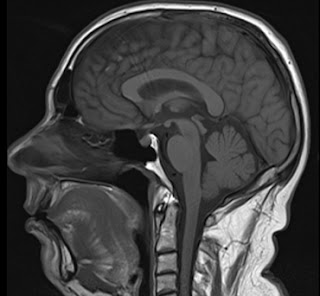
Old MRI image, not showing my stroke
If you think you are having a stroke, call 999, get help as soon as possible, please.

For more  information see stroke.org.uk

But this is my experience.

Misconceptions

I was surprised how much people don't know about a stroke. I ended up writing a long explanation for my family to cover it. One of my daughter's has worked with stroke patients in a care home and was "D'Uh!", but I think it helped the rest understand.

One of the things I found difficult was people asking "how are you feeling now", and "get well soon". A stroke, like most "long term" illnesses, is very different to the average illness. It is not like a cold, or even like a broken leg.

Basically - I feel fine. I actually "felt fine" the whole time - I just could not speak for about 4 hours. Maybe, and not even that much, a little tired, and that is it. I don't feel ill at all.

But also "get well soon" is not really a thing in the same way. The damage is done. The "getting better", in terms of brain cells that recovered from the lack of oxygen, has happened, within the first few hours. Yes, there is some re-learning stuff my brain could do over a longer term, maybe, if I am lucky. In my case I can tell my speech is not quite back to normal, but just the occasional word tripping me up. That may never go away. For worse strokes there may be possible rehab and physiotherapy that can help some recovery over time. But the whole process is very different to the "get well soon" you would apply to someone with a cold.

The usual platitudes for someone that has been ill or injured are not ideal, and even wind me up slightly as it is hard to give the simple answer. Sorry.

Background

I have been doing well. I have managed to lower my weight steadily over the last six months, doing more exercise. I have managed to keep my blood pressure and blood sugar well under control. Ticking all the boxes. No reason to have a stroke.

COVID

I made the mistake of going on a cruise. I did take quite a few precautions, including avoiding a commercial flight, not having to queue up for anything (yes, it was one of those cabins at the top of the ship that gets you a personal escort to the front of queues) and masking up in crowded spaces. Sadly I did go to the bar, and even with a table at the end out of the way and the small group of the same people, one of them got COVID the day before me. The two people on the cruise with me did not. Very unlucky.

But COVID is just like a nasty cold, and over in a week, right?

Wrong!

Yes, the main symptoms, in this case a severe fever and cough, cleared up a lot in 3 or 4 days. I was left with a nagging cough (which happened last time and lasted a few weeks), and a bit tired.

I'd like to thank Mike and Simon for ensuring a supply of pizza, starbucks, and paracetamol turned up at my cabin door.

But on returning from the cruise I realised my blood pressure was unusually high.

Mistake 1: I should have contacted my GP and got something done about it, even if only temporary while the COVID symptoms clear up finally. That said, blood pressure on its own is not what triggers the stroke - it is likely COVID causing blood clots - but the high blood pressure is a risk factor and an clear indication of COVID messing with me still.

Stroke

As seems to be a common thing now with COVID - I then had a stroke. It was 11 days after first COVID symptoms.

It was fortunate that I had reason to go and talk to someone - I managed to leave my glasses in a shop in town and walked back to find them. If not, I would have been sat at home and not had any cause to talk to anyone. When I got there I realised I could not talk properly! My speech was really slurred. The people in the shop did not know me and so did not know that was not my normal speech.

I went home and double checked. I recorded myself and played back. I could smile. I could raise my arms, and legs. But my speech was slurred. Oddly it seemed worse to me when speaking than it did listening to the playback, but even so, the playback was slurred. I have learned that some people cannot tell their speech is slurred, which is interesting - I definitely could.

Given the horror stories about delays with ambulances of late I decided not to wait, and just walk to the minor injuries unit at Nevill Hall. It is 20 minutes or so, but I am pretty confident it was quicker than an ambulance would have been. Obviously in different circumstances I would have either been driven by my wife (she was out) or called 999 for an ambulance. In hindsight, starting to walk, and calling 999 from my mobile, may have been the best of both worlds - though "calling 999" with dysarthria may well have been a problem.

Yay! I learned a new word, dysarthria.

Nevill Hall

The MIU were good. I had to type on my phone to be understood - I did this whilst walking to the unit anyway, so was ready. Fastest triage ever - I did not have time to sit down. I was on a bed, on a drip, CT scan, and then very quickly in ambulance (blue lights!) to The Grange hospital, 20 minutes away. They got me on aspirin pretty quickly.

The Grange

Being in hospital sucks, I know. First night I was in resus in the emergency department on a monitor and there is no way to get any sleep. Then was transferred in morning via "Majors" and "Assessment" before going on to the actual stroke ward.

I spent three nights in hospital, bored silly. I had a book, and my phone, but still bored. The ward was good though, a shower, reasonable food, comfortable bed. But 3 hourly obs (blood pressure, pulse ox, temp, pupil response) makes a good night's sleep impossible.

The stroke tests get very tedious...

  • Smile
  • Stick tongue out and move left/right
  • Raise arms
  • Raise legs
  • Grip
  • Push (arms and legs)
  • Pull (arms and legs)
  • Where are you?
  • What month is it? (yes, even at 1am on 1st October, I passed)
  • Who's the King?

Now, I know they are important test, and I know the staff are doing their job, honest.

The real problem is a stroke is very different to a lot of other illnesses. At this point, I was not "ill" any more. I felt fine. My speech was 99% back to normal after only a few hours on Friday. Being in hospital when not actually ill is extra frustrating.

But the staff were great, and have my thanks.

Some minor niggles

There is equipment for monitoring patents. It does blood pressure, ECG if needed, pulse ox. On Friday I was plumbed in to it. But after that it was used for regular obs, so blood pressure cuff and pulse ox sensor. The problem is that they left it switched on. This means a beep every 5 seconds to warn that it is not "connected" to the patient any more. It is a matter of a button press to shut it up.

There are two problems with this!

  1. The noise. Four of these on the ward all doing a beep every 5 seconds all the time, all out of phase. This is not conducive to patient care and getting rest.
  2. The more serious issue - these things beep for a reason. They are alerting that something is wrong (in this case, simply that they are disconnected). By ignoring the beeps, becoming deaf to them, they lose any usefulness - the beeps can no longer be effectively used to actually warn that something is wrong any more. It has to be bad practice to ever leave any such equipment generating an ongoing warning beep.

There are some cases where a beep is not a warning as such, such as the heat beat beeps for the ECG when in ED, where the beeps can allow the attending nurse to instantly hear even subtle problems. But on the ward there was nobody on ECG, so not the issue.

I did manage to get them turned off, but had to ask on several occasions, and the stock answer is "we have to monitor some patients", and I have to explain that I understand, but these are from machines that are not monitoring patients!

The other obvious niggle is that I was only really there for three days, not for observation, but because of the time it takes to get an MRI, Doppler scan, and see occupational health and speech therapist. That could have all been done after 24 hours, but a lot of stuff is not done at weekends. At the end of the day, that is just how it is.

Oh, and being supervised taking my regular meds felt like I was some sort of naughty schoolboy! They also struggled with the notion that I set my own insulin dose, and adjusted it because being in hospital was different (led to a hypo in the night, so lowering the dose).

Stroke doctor

The stroke doctor basically explained it was a mini stroke. He did the checks again, and a number of perceptual checks. He explained that I would be on aspirin for 3 weeks, and blood thinners permanently, and some slight changes to other meds.

However there were a couple of oddities. He was a stroke specialist, but still, I was surprised.

  1. He commented how my HbA1c (overall blood sugar measure for diabetics) was really good, and maybe I should not be on meds/insulin for diabetes. This makes no sense to me (or my GP) as the very reason my HbA1c is good is because I am on the meds and they are working!
  2. He asked about migraines, and I explained I get an aura only, one side or the other. He said "so one eye or the other". I corrected him that it was one side of my vision, or the other, and not one eye or the other. He continued with "one eye or the other" so I gave up.

Followup information

This was another surprise. I got following information on (a) not driving for a month, and (b) speech therapy. But I got absolutely nothing on strokes. No "what is a stroke? what causes a stroke? What risk factors can you mitigate in future? Why do you have blood thinners?" etc. I can research these myself, but why no information pack? I bet a lot of patients leave confused about what has happened and what they should do about it.

Work

Obviously I work - I run an ISP. But my management team are very good, so have no problem with my trying to rest for a few weeks, or longer if I was to be seriously ill. I am obviously keeping an eye on things as "taking a rest" is not quite the same as "doing nothing" which would wind me up even more.

COVID recovery

Right now, my main concern is the COVID symptoms - the cough and high blood pressure. Especially the high blood pressure. I have been working with my GP - higher dose of some meds while it is a problem, and that seems to be working now. Oh, and saying "stroke" to a GP receptionist seems to be a magic spell for getting an immediate call back from a doctor.

People need to realise COVID is still very common and still very serious. Whilst my case was "minor", a stroke can be a serious long term impact on someone's life, and the lives of their family, for the rest of their life. In some ways it can be worse than COVID just killing people off (and I say that as someone that watched my father die of COVID just a year ago).

It is not just a cold. Please take it seriously.
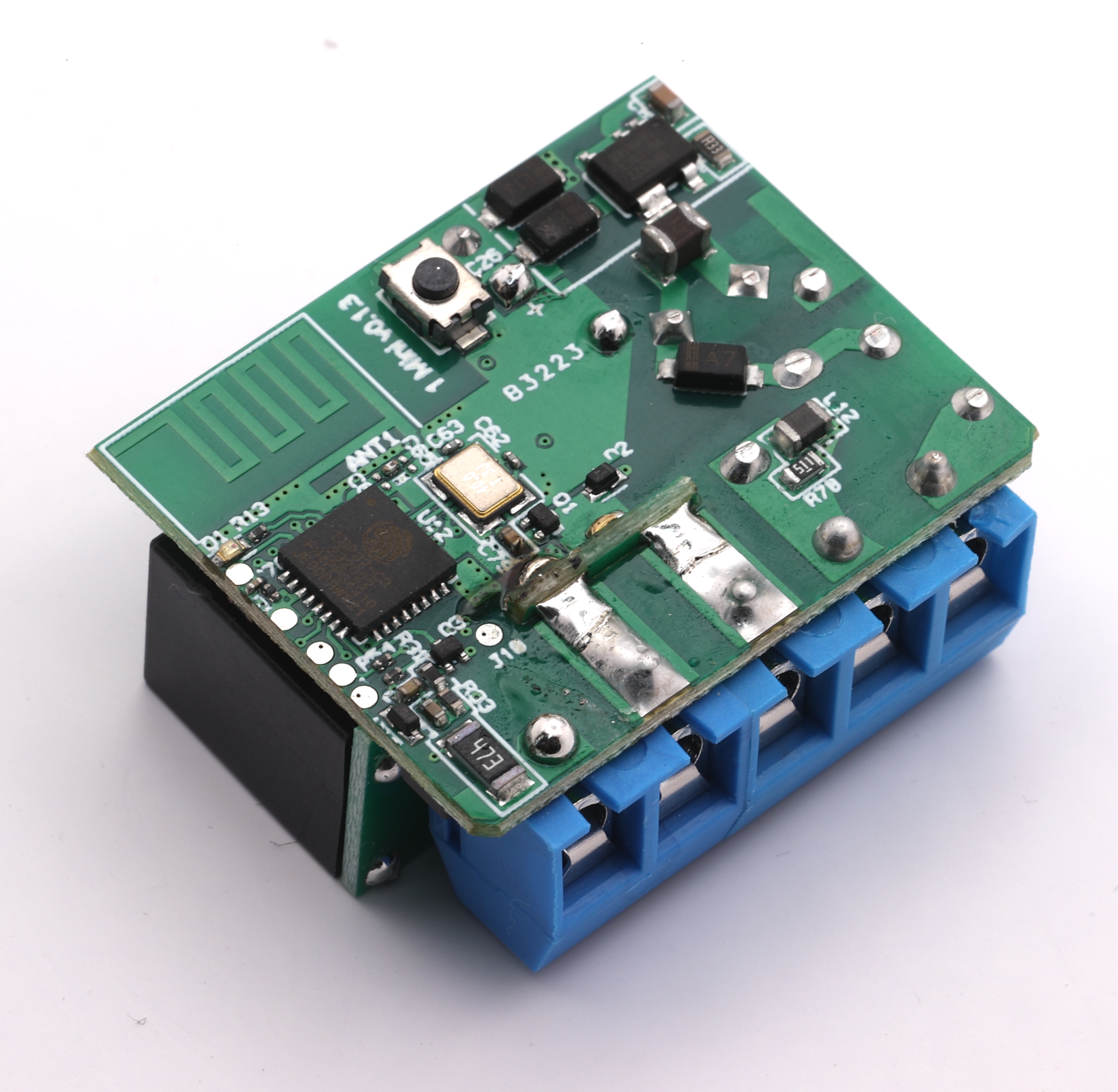
2023-09-27

Dialling the gate

People will know I am a slight Stargate fan (!), and I like making PCBs. So, well... Latest is...

LEDs

First off, the LEDs. There is a very popular LED format, a WS2812B chip and RGB LEDs in a package. These use a serial daisy chained control channel allowing 256 colours of each of Red, Green, and Blue, to be loaded individually to a whole chain of LEDs. This design has 372 LEDs.

There are standard libraries to drive these, but I have discovered the ESP32 S3 is better as it uses DMA for the "remote control" hardware that is used to drive the data for these LEDs.

You can get these on tapes, and rings, and so on, usually 5mm x 5mm, or 4mm by 4mm, and I had even seen some 2mm x 2mm, but was surprised to find they are now available in these tiny 1mm x 1mm format. This ring design has a 100mm diameter centre hole.

They also usually need 5V power, but amazingly these small 1mm x 1mm modules work on 3.3V (or 5V), which is impressive (Blue is usually the voltage hog).

They are also very cheap. Part XL-1010RGBC-WS2812B, LCSC Part C5349953.

Alignment

My first mistake with the LEDs was making the layout simple, so a grid of these LEDs were one way up on one row, and the other way up on the next row. This allowed GND to be between two rows, then VCC between two rows, and so on. I put caps at the ends of the rows (which works well). This allowed me to pack them at 1.6mm spacing.

This was impressive, but I missed the (apparently well know) issue that the LEDs are placed within the 1mm x 1mm space, so for example Red is one side, and hence an all grid red looks like this, not evenly spaced.

They have to all be the same way around to avoid such issues.

Diamonds

I tried doing the same way and really a pain to track. The trick is to actually place them at 45 degrees, diamond style. This makes tracking really simple.

This allows a track at the top for GND, and at the bottom for VCC, and a link from LED to LED corner to corner for the daisy chained data line. Shown here I have vias for extra power. With thin tracks between the pads of the capacitors (expected to be one per LED) it makes for a really neat layout.

Grids

Grids were easy, and grids of LEDs like this are simple, with 2mm spacing (no caps), which is not bad. Caps added at end of row or column.

Apart from tracks joining VCC and GND top and bottom, or side and side, I actually created zone fills to make for thicker overall power tracks.

The latest design at 2mm spacing is 10mm x 18mm for a 5x7 grid, and allows them to be placed next to each other for a whole row at 2mm spacing, LEDs at the top and bottom of each column.

Rings

The other thing to do was rings of LEDs.

The principle is pretty simple, tracks (this time arcs) for GND, data, and VCC. Some zone fill for VCC and GND, again arcs (well polygons and lots of points).

Adding vias is fun, and I ended up with code that puts them off to one side if diodes and caps too close together (as above image) or in line in the GND/VCC tracks when enough space.

A simple ring with evenly spaces LEDs and caps is easy, but then I decided I needed some grouping of LEDs together with specific tighter spacing (the chevrons in the top image).

I also had to cater for the fact that power vias from one ring could clash with some of the next ring, and so omit some that were too close.

C code

If you have tried doing this in KiCad, it is far from easy - even with the grid locking and simple spacing like 2mm, it is hard, and making a ring with 39 LEDs, i.e. 4.6153846 degrees between LED and cap and LED, is, well, totally impossible. No chance doing it manually at all.

So, obviously, I ended up making C code, parsing in the PCB file, and moving LEDs and caps and making tracks and vias and fill zones. I have code for grid layout and ring layout now.

The gate

Working out the exact animation for the gate will need a bit of trial and error I expect - I cannot actually spin the symbols, so some poetic licence involved, but easy to "spin" the rings of 117 LEDs.

I have actually gone for a number of rings...

  • 117 inner rings, this is 3 per gate symbol, so makes for a nice "1 in 3" spin effect and allows the inner to be lit up and made sparkly for the gate open.
  • 39 gate symbol ring, so I can light individual symbols during dialling (seeing as they don't spin).
  • 18 ring for bottom of engaged chevrons (9 chevrons, so 2 per chevron).
  • 117 outer ring, again for spinning, but also can be two for chevron when engaged, and 3 for chevron end when not.
  • Two 18 rings for chevrons getting wider.
  • A 45 ring, so 5 per chevron, for the lights at the edge of the gate when selected.

I think making it dial will be cool. PCBs ordered, so a week or so (maybe more, some holiday in China), and I can post video of the real thing.

Open source

This is all open source, PCB designs and code, but if you want to buy one of these, and a driver, let me know. I have 5 on order.

2023-09-03

Setting the temperature

My air-con can have a temperature set and aim for it.

  • It has a wide range of ± a few degrees which I don't like.
  • It is not setting temperature by me, it is basing it on some sensor it has.

To fix this I have used an environmental sensor - on my desk, and for my bedroom, on my bed head. I then control the air-con - telling it I want it higher or lower than it thinks things are, so as to aim for the right temperature by me. It works well most of the time and keeps the temperature very close.

That is my bedroom, last night (cooling), units in ℃, so maybe ±0.2 ℃ at most. Good.

I also have radiators for the winter, and they have the same fun, driving the valve on the radiator with some prediction.

Which to use for heating? air-con (heat pump) or radiator... Bearing in mind some of the house does not have air-con, so has radiators anyway. I don't actually know which is most cost effective / efficient. But I can choose. Have systems in place to make sure they are never fighting each other :-)

Per room radiator control

One of the key things is per-room controls - this means a temperature sensor in the room, and a radiator control, and some way to tell the boiler that one of the rooms needs heat. We have two heating loops (up and down), my daughter has two (left and right!). But for each radiator there is one boiler control that is needed.

The hard way

So, the hard way, I have my fancy environmental monitors with a display. They have a config for temp targets throughout the day. I have systems to override for empty rooms. Using the light switch marks a room in use for the day :-)

They talk MQTT to a Shelly running Tasmota that controls the radiator. So needs an MQTT broker.

The Shelly talks MQTT to a FireBrick to say radiator is on/off.

The FireBrick has a set of profiles, and any one in each loop will cause a message to another Shelly running Tasmota to operate the heating loop valve.

This triggers the boiler as needed.

It works.

It is not cheap or simple - the env sensors cost, the FireBrick costs a lot.

The easy way - maybe

So I am working on an easy way - my daughter happens to have a FireBrick, but even so I am trying to make a really easy way to do this. Not all of my kids have one (?!).

The first step is the reference temperature. A sensor that can be placed sensibly, e.g. by a bed.


I had found some nice industrial (BlueCoinT) ones at €31, but now have found, thanks to a recommendation, some stupidly cheap ones on Amazon. They are only £9, and even cheaper on AliExpress. They can be refreshed with sensible code.

The next step is controlling the radiator, and something like a Shelly Plus Mini would be ideal. Not sure of price yet, but the normal Shelly Plus 1 is £16.49. Whoa, they used to be less than that! Interesting. The Mini may be less. We'll see. But up to under £26. The radiator control itself is something like this, £19.63

So yes, we are up to £45 per room. A few more £s for back box and fused spur box for the Shelly mini by the radiator. And one Shelly at the boiler.

The comms can all be BLE. Sensor to Shelly, and Shelly to boiler control Shelly. Just needs a bit of software.

Not ideal, but £50 per room for exact per room heating control is probably quickly worth it. Simple web interface (or maybe even HomeKit) for unoccupied rooms, and controls for times of day and target temperatures via a web page. This can quickly save on heating costs and make things more comfortable.

It always amazed me people ran their house with one thermostat on the wall in the hall.

2023-08-30

What counts as R&D?

One of the things a company can do in the UK is claim some tax benefits for spending some of the company resources on R&D. It is an incentive for companies to do R&D.

As a company that does a lot of R&D, we work with a really good agency on this, and get some tax credit. This works well, and is indeed an incentive for us to do more R&D.

This year the rules have changed slightly, and I noted a couple of them. It is all a bit open to interpretation, but a couple of the points seem a bit odd.

Open source

For a start, if we, as a company, did some purely open source stuff that was not direct benefit to us - by way of giving back to the open source community, it seems that would not qualify for R&D tax credits. It has to benefit the company. Thankfully this is not really a problem as pretty much all of the open source stuff we do is used in house and so benefits us directly as well. Some of the stuff we don't use in house, is actually stuff we then make and sell, so a benefit to us. But it is a disincentive for doing something purely open source.

Super human engineers

The other one that is odd is that things are not R&D if they would be apparent to a competent engineer in the field with publicly available information.

Well, we employ competent engineers. everything they do is apparent to a competent engineer. It almost sounds like, to be valid R&D, we need super human engineers, which seems a bit much.

We had a lot of discussion on this - one thing is the "publicly available information". This has meant we have focused a lot on things where the publicly available information is wrong or incomplete. And notably where what was "apparent" to the competent engineer was in fact wrong when tried.

Though one other aspect is that we think we can validly say that anything we are doing based on closed source designs and code is something that qualifies because that closed source is not publicly available information. None of it would be apparent to our competent engineers without access to that closed source information. So again, this seems to be discouraging open source.

Even so, the end result was a good meeting today, and plenty of R&D work.

2023-08-25

Amazon done wrong

We sell on Amazon, and for that I'll apologise at the start, but it does provide some convenience to some customers and mostly works.

A few weeks ago we got an email saying we have to upload dome documents or they will close the account, and several ongoing reminders. Oh shit...

The problem is that the staff, including me, have a login to the seller account and can do 99% of things on it, as needed, but we could not do this as it had to be the main seller account. OK, so log in to that. Easy.

Except it wants to SMS a number to one of two numbers. Both were set up (and so worked at the time), but are 01344 (i.e. landline) numbers, and between when set up and now Amazon have obviously fucked up their SMS stuff and cannot SMS either.

The interworking of SMS really is a shit show and needs OFCOM to actually do its job and ensure it works properly.

But they also for calling them with a code - yay - except that also does not work - no clue why. Both numbers valid for SMS and calls, and they do neither.

So I tried the "remove 2FA" and sent pictures of passport, or something. My accounts manager did the same several times. No joy.

Every single chat was just crazy, and got to being daily. I mean I am tempted to publish them - they are so mad. One of them insisted I wait 24 hours after trying before contacting them - I said I had done that - he asked why I did not contact them after waiting 24 hours - and I explained I did - this is me contacting them!! The chats were like that. I don't like to judge people as "stupid", honest, people are only sensible in the areas they know, and that applies to all of us. But really, these chats were "special".

Just to be clear - the only reason I could "chat" at all is I had a working amazon account from which to chat. If not I would be screwed.

I have my case handled and referred to these, all of which did not reply at all!

  • Internal escalation team
  • Account recovery team
  • External escalation team

I finally got someone that insisted that another "remove 2FA" should work, and I tried it, and, well, it did. But the instructions were clear - once done I could log in with just a password.

This was a lie. I logged in, and it said "Enter verification code. For your security, we've sent the code to your phone ***-***-**23" which basically means 2FA, so not removed, but also a number I don't know. Not either of the two numbers before.

Many more chats. No way to progress this. Doing the "remove 2FA" again stalled as it needs the code sent to *23 to get as far as uploading a driving licence even. I kept on, emailed in again, and finally it changed.

Now I have option for OTP by email or by SMS to *23, yay, but then it again does "Enter verification code. For your security, we've sent the code to your phone ***-***-**23" as well. So email and SMS now! (yes, when I got SMS working it wanted email too, so yes, both now needed!).

Had there not been an actual mobile *23 I really think we would be screwed. They have zero way to sort this from what I can see. Removing 2FA is "still do 2FA using a *main* mobile number" which you cannot change until you log in!

Turns out, after some research, checking staff lists, and pestering someone on leave and at a party (really, thank you Mike), I found someone that had a number ending in 23, and they were indeed what was on Amazon. So they let me know the code. Yes, that is being fixed, they should not have been on the main login, really. History from when first set up.

So finally I am in - it took a couple of attempts, but now the 2FA is sorted.

Phew.

So back to step 1. What is it they need.

Well this...

Yep, it is a sort of Farage test I think!

Obviously I click Agree and submit.

And, well, predictable...

So, err...

So another chat, and really, I am at a loss on this chat...

Ok, long winded, but basically no clue why this was an issue "not understandable" somehow, and actually, no, there is no way to upload a screenshot.

Eventually got an email and replied with a screenshot. It is a "don't reply to this" email address, FFS.

2023-08-21

LIGHT HAS A SPEED - SO WHY NOT DARK?

I was looking at today's xkcd, and am reminded of a Terry Pratchett quote: [The science of Discworld, Terry Pratchett, Ian Stewart & Jack Cohen, ISBN 9780091886578, chapter 22 "Things That Aren't"]

LIGHT HAS A SPEED - SO WHY NOT DARK?

It's a reasonable question. Let's see where it leads.

In the 1960s a biological supply company advertised a device for scientists who used micro-scopes. In order to see things under a microscope, it's often a good idea to make a very thin slice of whatever it is you're going to look at. Then you put the slice on a glass slide, stick it under the microscope lens, and peer in at the other end to see what it looks like. How do you make the slice? Not like slicing bread.

The thing you want to cut - let's assume it's a piece of liver for the sake of argument - is too floppy to be sliced on its own. Come to think of it, so is a lot of bread.

You have to hold the liver firmly while you're cutting it, so you embed it in a block of wax. Then you use a gadget called a micro-tome, something like a miniature bacon-slicer, to cut off a series of very thin slices. You drop them on the surface of warm water, stick some on to a microscope slide, dissolve away the wax, and prepare the slide for viewing. Simple ...

But the device that the company was selling wasn't a microtome: it was something to keep the wax block cool while the microtome was slicing it, so that the heat generated by the friction would not make the wax difficult to slice and damage delicate details of the specimen.

Their solution to this problem was a large concave (dish-shaped) mirror. You were supposed to build a little pile of ice cubes and  'focus the cold' on to your specimen.

Perhaps you don't see anything remarkable here. In that case you probably speak of the 'spread of ignorance', and draw the curtains in the evening to 'keep the cold out' - and the darkness.

It occurs to me that it would surely work as you would expect. Whilst you cannot focus cold on to something, you can cover part of the area that would radiate heat from the environment to something with a mirror, and that mirror pointing at ice cubes means that not as much heat is radiating from the ice cubes via the mirror to the target as would be otherwise. But heat from the target is radiating to the ice cubes that absorb that heat. The net flow of heat would be from the sample to the ice cubes for a large chunk of the area surrounding the sample.

But this would mathematically be the same as considering cold radiating from the ice cubes to the target via the mirror. I suspect the maths works out exactly as you would expect for focusing cold just the same as it does for electron holes.

Yes?

Missing unix/linux/posix file open option

What I would like is a file open option for "create replacement file". The idea is that this makes a new inode in the same mount p...