2022-01-30

More on KICad 6 and PCBs

I have been updating all my PCB designs to allow for using the more commonly available LMR16006 with variable voltage, rather than the fixed 3.3V regulator. All done now.

But I have also made a couple more boards.

For a start, an ESP32-WROOM-32 board with more GPIOs. The previous generic board was this.

It has 6 pins, GND plus 5xGPIO with some links. I have updated the silkscreen to have GPIO numbers all over the place as it is a pain to find them on older boards if not printed on the board!

But I decided a more powerful generic design may be in order, so did this new one today...

This is a tad bigger, but 16 GPIO pins. Yes, one each side is pre-linked to GND, but can be cut. And options to link to DC supply or 3.3V are always useful. Again, an RGB LED on board. And I have labelled all the GPIO numbers. This should be useful.

But this has been a busy weekend, and I have also made this...

Now this is a fun board, an interface for an ASR33 using 20mA current loop. It uses some simple ICs that are aimed at providing fixed current driver for LEDs, but seem ideal for this use. For avoidance of doubt this is not the same as 4-20mA current loop used for some control systems (an analogue signal level), but a simple make/break on 20mA, and used for teletypes 50+ years ago.

All of these will be a little over a week to arrive, so fun to test when they get here. I'll post more, specifically on the ASR33 board, once I have them.

To be honest I am amazed how easy KiCad makes it to just knock out a circuit design, do PCB layout, and be all ready to order actual boards.

2022-01-20

Sudden braking

The concern is that a car, turning in to a side road, may suddenly brake to allow a pedestrian to cross the side road, and this could result in a car from behind failing to stop and cause a collision ("rear ending").

This is obviously not good!

Yes, the car behind should allow enough space, and is in the wrong here, but even so, sudden braking is not good and should be a voided.

So why sudden braking?

The obvious reason for sudden braking is when the driver finds circumstances changing unexpectedly. If they can predict what is happening well enough then they can slow sensibly rather than suddenly brake.

Under the current Highway Code, if a driver turning in to a side road sees a pedestrian on the pavement about to cross, the driver has to make a guess. They have to guess if the pedestrian will wait, or cross. Given the rules for pedestrians expect the pedestrian to look for cars turning, and the "Green Cross Code", etc, the driver may make the reasonable assumption that the pedestrian will wait. The driver proceeds on that assumption, not slowing much, expecting to make a moving turn in to the side road. However, if the pedestrian starts to cross, the driver has to brake suddenly because at that point they are required to give way to the pedestrian (§170 Highway code). This is unexpected and so causes "sudden braking".

As I say, sudden braking is not good.

The solution?

Thankfully, as of Jan 29th 2022, the rules are changing. The new Highway Code rules say §170: "give way to pedestrians crossing or waiting to cross a road into which or from which you are turning".

This is a change, in that you now give way to those "waiting to cross". So now, when turning, if you see a pedestrian waiting to cross you not longer have to guess if they will wait or cross. You have to give way to them, to wait for them.

This means you can cleanly signal, slow, and wait for the pedestrian. No unexpected changes in circumstances. No sudden braking. Safer for everyone.

So yes, the Highway Code changes finally address this "sudden braking" issue, at last.

2022-01-18

Power to the people

This is an initial post on a little project I have with monitoring the power (electricity) usage here at home. But first, a bit of background, and smart meters.

Smart meters

In my last house I was, like most people, constantly badgered to have a smart meter. I did have one installed eventually, as it happens. But what is especially odd is the way they are marketed - as "money saving". From what I can tell the main "money saving" aspect is simply that you know how much power you are using in real time, and so can make savings by using less power. You don't need a smart meter for that (as you will see below).

Now, there are other aspects - notably there are now some companies with some special tariffs. My son's is a good example as he has a period over night with very cheap (5p) electricity for charging his car. That alone could be done with a classic "economy 7" type meter, but some of these tariffs are more dynamic, and even link to the car to tell it when it can charge, offering even better tariffs. So yes, there are some ways a smart meter can be advantageous. If you don't have an EV, then maybe less so, just saving using a night tariff for washing machine, tumble dryer, or other high usage stuff, but that is not always as simple as it sounds.

Of course the big downside, that they don't mention, is that the smart meter has a contactor that means the power can be remotely turned off. This is a danger because it can happen by mistake (people mistakenly switched to pre-pay tariff without any means to pre-pay), or because of hacking, which is always a risk. I suspect if that was explained there would be a lot less take up.

But what really does annoy me is how smart meters can so easily become dumb. Shortly after getting one, I switched to another energy provider who simply could not use the smart meter - so no special tariffs, and having to submit meter readings.

When I moved to my new house, there was already a smart meter in place (only for electricity though), and surprise surprise it too was dumb, with the power company I was using (a different one again) unable to read it, and so I have to submit readings.

So, without the detailed live reporting, and finding that the electricity bill is quite high here, and expecting a significant increase in per unit costs, I decided to look in to our usage and see how to make some savings.

Energy monitoring

It turns out that a bit of energy monitoring is not that hard. I have seen projects to watch the blinking light on the meter, but that means power to such as device, and our meter is in a cupboard on the outside, so not easy. What is simple is using a current clamp.

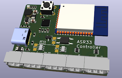
I am using the Shelly EM devices, these can take two clamps per device.

As usual, the Shelly software that comes with it is perfectly adequate. There is also software you can get that integrates with Apple HomeKit. However, for consistency of the various IoT devices I have (over 100), I re-flashed with tasmota software.

The energy metering is logged to MQTT nicely, and so easy for me to code logging and graphing of the data.

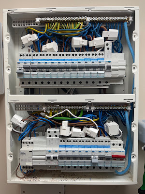
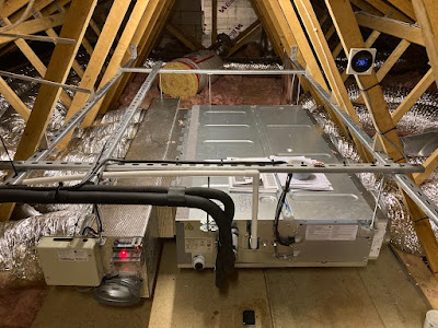
Using one of these, and the 120A clamp (there are 50A and 120A which are simply for different size cables) it is easy to clamp the main incoming tail, and get total electricity usage. But that would only give me as much detail as a smart meter, and I wanted more. So I put five of the Shelly EM, a total of 10 clamps, in a deep two gang back box below my consumer unit, and fitted 10 clamps.

This is not quite enough to monitor all usage, and in some cases multiple circuits go via one clamp, but it has allowed me to break down my usage pretty cleanly in to different areas of usage in the house, and so make some changes.

Making some graphs


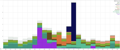
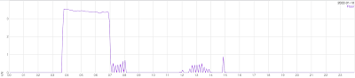
Having data sent to MQTT made it easy to log the usage to a database, and so make graphs (in SVG), which can be for multiple sensors, for a day, a month, a year, etc. So the graph above is one day. By colour coding each area some usage really does stand out.

Consistency

The first thing I wanted to do was make sure the metering was consistent. The hatched area is the total, from the incoming tail, and shows at the top where the various other values add up to less than the total. This initially puzzled me as only the lights were not being monitored and it was around 500W difference which was way too much for that. It also seemed to be all day and night.

It turned out one wire was missing on the air con clamp, meaning that (over night) was missed, and also one set of sockets was missed out, impacting all day. Once these were fixed (part way through that day) the discrepancy is nice and clean - almost zero over night as typically one light is on, and a very sane low level for the lights during the day. So I am happy the measurements are consistent now.

Just looking at that one day, you will note some big green blocks on the left, some purple, and a lot of dark blue. These are hot tub, heated floor, and bat cave respectively. But let's break down some of the usage in more detail.

Hot tub

The hot tub is one concern we already had. Shutting down a hot tub is not a simple matter, especially if it is outside where things could freeze. Also, there is no reason not to use it in the winter (even though it is outside), but perhaps not as often. So saving money is not so simple - but understanding how much it uses is useful.

The usage will depend on the temperature, and is mostly just keeping it to temperature with the heater. It is well insulated. When idle, its usage is around 14kWh/day (i.e. around 580W average). At present that is about £70/month, but will go up soon. Not ideal, and clearly something we could consider shutting down if ever we needed to.

One idea was keep it running but at a lower temperature. That does work, indeed it was tested during that day hence the usage mostly being in the morning. The impact was half a day of no heating as the temperature dropped (we set 5C lower), but then the ongoing heating the next day was very similar to that at the higher temperature (only slightly longer gaps). I suspect if we lowered it as low as is sensible we could indeed save power, but if we are still using it some of the time, that is not really going to help. It can take a couple of hours solidly heating to get back to temperature, so using every couple of days it will probably negate a lot of the savings made.

FYI, we noted it only uses 11A heating, and were surprised at the rather beefy installation. This is until we turned on the pumps! It has several jets, and when all on, and the heater on, it can, indeed, pull over 28A. I guess pumping water takes a lot of power. Worth noting. It also has some low usage for circulation pumps that it runs twice a day (and also whilst heating, by the look of it).

Heated floor

The other obvious high user was the fact we have an electric heated floor in the kitchen. It is slate tiles, but this is also the only heating in that room if the door is closed, which is not very efficient.

The graphs made it clear that the floor was using a lot of power. It pulls 16A, and was, in the morning, using a lot.

A very small change of leaving the kitchen door over night left the kitchen warmed from the gas central heating in the house, and made this a lot less demanding. But I also found the temperature sensors were not remotely calibrated, and several degrees out, and also it has an "eco" mode, which is not that clear but did change the usage, and even the clock was wrong and starting far too early in the day.

I expect some more tinkering can save some more without the floor being cold, and it depends, once again, on environmental temperature. We have got it from a worst case measured so far of 28kWh/day down to 8kWh/day now.

Bat cave

The bat cave is simple, it is an outbuilding we have, and the only thing in it is a light (switched off), a temperature sensor, and a freezer, so yes, the usage is very low all day. 0.47kWh/day (20W).

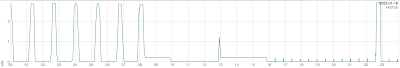
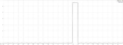
But you will have noticed on my first graph a big dark blue block... It looks like this :-

From this you can probably work out exactly when, and for how long, my son, with his EV, visited, and used the charger on the wall of the bat cave :-)

Other usage

Obviously a number of other things stand out, when used, notably the washing machine and tumble dryer. Even without separate sensors for all of these, it is very simple to see the individual use cases and get an idea of the cost of their use.

My network

I also have, in my loft, on its own circuits, a server, a NAS, fibre termination, firewalls, and switches that PoE all the access points and CCTV cameras, and various other things. This is a simple steady 8½kWh/day (350W). Not insignificant (£40/month) but worth knowing.

More?

I will post more once I have some months of data, I am sure. One of the things I am doing is fitting more of the nice Shelly Plus 1PM switches for lights and some specific devices to get more fine tuned break down of usage. I am also planning solar/battery soon, and will post on that.

The linux tools (taspowerlog and taslowersvg) are on GitHub.

2022-01-13

Do you want chips with that?

(for the help of Americans, "chips" mean "french fries" in the context of asking someone if they want "fries with that", but also mean "microchips" in context of electronics, sorry to have to explain that)

For a lot of my little PCB designs I need a voltage regulator, something to provide a clean 3.3V DC power for things like an ESP32, which means over 0.5A peaks for WiFi. In this case I have a nice PCB footprint using an LMR16006 which is 600mA at 3.3V, and has proved very reliable and easy to use.

There are many reasons for picking this, even though a slightly pricey solution. For a start it is a leaded chip so can be hand soldered. To be honest I am doing things using solder paste and a stencil much more now, so far less critical. But it is small - the whole footprint for the regulator is small.

Some time ago I got 100 off of the parts and put in a draw and have used on various boards, but I am running out. It is only a few pounds for the parts. What none of us knew is chips would become somewhat hard to get all of a sudden. Had I had any clue I'd have got several hundred and even kept them on tapes so could be used for production. Hindsight.

So now I am stuck. I have limited supplies and nobody has stock until late 2023 now. So I need to find an alternative. Something small and easy to use. Something available that won't run out! Something offering at least 600mA of 3.3V. Something with a nice wide input voltage range. Something easy to hand solder, or at least easy to solder paste and cook by hand. Also, as some boards are battery based, we want very low idle current, which this manages quite well and automatically.

I saw a LTC7103 suggested by someone - way overkill, but very cool. Also rather pricey. I looked a little while ago, and thought that it was good that you can still get them. Today I thought I would try this out, and get some, and make some boards, only to find Mouser have 7 of them, and a silly price, and no more until August at the soonest.

So I need to find something else. I am not an electronics engineer, honest. I know that whatever I get means new PCB layouts for various boards. I am starting to get a feel of how much hassle this all is right now. Oh! to be back in the "normal" days of next day whatever chips you want from a range of suppliers.

I expect I'll pick another solution some time soon, and make some boards, and maybe even hoard a few hundred of whatever I pick!

Of course the same is happening to the new FB9000 FireBricks, which are also waiting on chips. All fun and games.

2022-01-12

Air-con, second attempt

Sadly it has become clear that the system installed is simply not going to work. So we are having it taken out, but keeping the Lossnay for fresh air.

Why on earth Mitsubishi would have a system supplied with dedicated controllers that have a thermistor in them, and a setting to use the controller temperature, but not actually support that, is beyond me. It does not even give an error, it shows a plausible, but wrong, temperature. But apparently they cannot support controlling from the controller, and so the two rooms off each system approach is just not going to work.

So now I have to start again with another air-con company. Maybe we'll get something before the summer.

All good fun. But they have sent interesting pictures of previous installations, which look cool.

So I'll post more when I have it...

2022-01-04

KiCad 6

I am using KiCad for PCB design, and it is pretty impressive, but KiCad version 6 has just been released.

There are lots of small changes, but all good. So I checked all my designs. Some tweaks were needed.

One of the nice things is I decided to look in to was making curvy tracks - mainly for the RF board I have - the PN532 NFC/RFID reader. RF is still voodoo, so no idea just yet if this is going to be an improvement or not. Hopefully the changed boards work just as well, if not better.

PCBs are like works of art, and a bit like coding, they can be tinkered with and fine tuned over and over again. KiCad caused me to start this again.

One issue was my antenna design - a simple loop. Previously I could fudge a "line" in copper on a footprint, and as long as the line did not cross the centre point of a pad it was not spotted by the DRC. The new KiCad does spot this, and so spots the antenna is a loop that shorts things. Well, antennas do that! I have yet to work out a way to tell it that this is a special case. So I worked around it.

What I did was make the 0603 links to the antenna part of its footprint. This means the loop can be a pad design with no pin name/number, and the other end 0603 pads (usually a 0R link) are the connection to the antenna footprint. That way it can pass DRC.

But the tinkering continued...

  • Removed the separate 0.1" connection pads as they fit in the 2.5mm pads and it means less copper near the antenna.
  • Re-tracking with curvy tracks and moving some away from antenna.
  • Changing layout so the RF Rx line is "cleaner" in that it has more space around it leading in to the PN532 and no ground plane under it.
  • Changed silkscreen - cleaner - indeed the "face" has no text. Removed the component designators as they are just clutter. Various tidying. Trying to make it look "distinctive" - did it work?
  • Changed LEDs so instead of abusing normal SMD LEDs and fitting backwards (face down) I have actual "reverse mount" LEDs instead. This should mean it is possible to use in a pick and place machine.
  • Cleaning up the BOM so I can actually get a quote for sourcing and assembly.
  • I hope you like the "eyes" :-)

We know these boards work well, and all of these tweaks should do no harm, and may even improve it.

So what next?

Well, I have the reverse mount LEDs coming Thursday, so I can work out the right resistors as they are higher current - also making sure the PN532 can drive them OK. I will then get some PCBs made to test all these changes - probably an express order PCBTrain to arrive Friday.

Once I have the PCBs I'll know if the new layout works as well as before, and if the LEDs work properly and so on. The 3D case design does not even need to change!

This leave the real next step - I have a BOM that loads OK on PCBTrain quoting tool, and gives pricing. I need to talk to them as it seems more for components that direct from Mouser, but I am sure that can be sorted. As with most components there is a shit lead time, especially for the PN532 chip. It does look like it will be not as cheap as I would like, around £30 a board assembled on small ish quantities (100), maybe £20 for 1000 off. So I am interested in if people want this. My plan for now is make some and sell at cost on Amazon.

They are a cool device for any hobby project and unlike some of the other PN532 boards they are designed to be used for access control, with tamper switch button and traffic light LEDs built in, and a small 40x40 size. Also, unlike a lot of others, they have BAV99 diodes to provide more ESD protection of the pins and LEDs.


Update: Parts came Wednesday - the new reverse mount LEDs work nicely, as does replacement crystal (as one we were using is not in stock). So new board design has been ordered to test the RF side, expected Friday.

Update: The new board works nicely, so proper boards with solder resist and silk screen are due in a few weeks.

Missing unix/linux/posix file open option

What I would like is a file open option for "create replacement file". The idea is that this makes a new inode in the same mount p...